Hello,
i received this amp, with blown ps, and one bank output.. Repaired ps, removed the whole damaged bank, and resolderer the other bank, because of bad solder joints..
The problem is now, that it pulls me up the -15V for the op amps.
On the board are only two op amps, they measure ok..
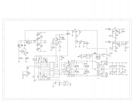
The LM7915 gets hot realy quick. Op amps stay cold. Between +and- on the op amps i measure 9Ohm.. Removed the lm 7815 and 7915.. Anybody has a schematic, where the voltage is used?
i received this amp, with blown ps, and one bank output.. Repaired ps, removed the whole damaged bank, and resolderer the other bank, because of bad solder joints..
The problem is now, that it pulls me up the -15V for the op amps.
On the board are only two op amps, they measure ok..
The LM7915 gets hot realy quick. Op amps stay cold. Between +and- on the op amps i measure 9Ohm.. Removed the lm 7815 and 7915.. Anybody has a schematic, where the voltage is used?
Ok, it seems that both op amps are burned.... Removed them, now voltage is ok... Very strange amp...never had this, that everything on one amplifier is burned.
For testing, yes. Op-amps, when subbed, can do some strange things. They typically work but not always.
Continue on this amp.
Repaired PS, installed new output transistors, pre stage, and op amps.
I have Pos. DC on the output of that channel, and the other only disorted low signal.
For the first i want to fix the dc.
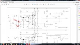
Iam now at the stage before the bias.
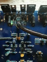
MPSA 92, i have on all three pins rail voltage.
On the side, with the disorted signal, i have rail on base and emitter. Collector is nothing.
Ground is sec. center.
Marked is the collector. How does it should work?
Repaired PS, installed new output transistors, pre stage, and op amps.
I have Pos. DC on the output of that channel, and the other only disorted low signal.
For the first i want to fix the dc.
Iam now at the stage before the bias.
MPSA 92, i have on all three pins rail voltage.
On the side, with the disorted signal, i have rail on base and emitter. Collector is nothing.
Ground is sec. center.
Marked is the collector. How does it should work?
Attachments
Last edited:
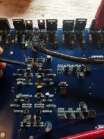
Each optocupler is for one channel. There is one optocoupler in the center, maybe this one drives both. If I remove the n Chanel jfets, I get audio.
How are they using the jfets?
For the center opto, what is the DC voltage across pins 1 and 2 before and after the mute delay?
For the center opto, what is the DC voltage across pins 1 and 2 before and after the mute delay?
Na, iam wrong. The center optocoupler is the Mute. Pin 5 fromt the Coupler goes to the gate of the J Fet.
Pin 1 and 2 has only 1.2VDC after a second. When power of, its slowly goes down.
Pin 1 and 2 has only 1.2VDC after a second. When power of, its slowly goes down.
Last edited:
J-Fet PN4391
Pin4 is +15V ground is sec. center.
If i Bridge pin 4 and 5, the mute is off, because the J-Fet gets 15V on Gate.
So i expect a damaged Optocoupler, if the 1,2V at Pin 1 and 2 is enough.
Pin4 is +15V ground is sec. center.
If i Bridge pin 4 and 5, the mute is off, because the J-Fet gets 15V on Gate.
So i expect a damaged Optocoupler, if the 1,2V at Pin 1 and 2 is enough.
Changed with a used coupler... Still the same
How many Volt i must have at Pin 1 and 2?
Is 1,2VDC enough?
Otherwise, pin 6 pulled down from something
How many Volt i must have at Pin 1 and 2?
Is 1,2VDC enough?
Otherwise, pin 6 pulled down from something
- Home
- General Interest
- Car Audio
- US Amps 2000x