
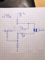
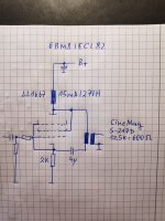
The input circuit includes g1, the cathode, and the 2k resistor.
The un-bypassed 2k changes the gain of the stage - particularly at low frequencies, where the inductive reactance of the choke and the inductive reactance of the output transformer primary might become a factor.
The un-bypassed 2k also changes the gain of the stage at high frequencies if either the distributed capacitance of the choke is too big, or the distributed capacitance of the output transformer is too big.
There are reasons to leave out a bypass capacitor.
There are reasons to connect a bypass capacitor.
Last edited:
Many thanks for the response. Just choosed this topology because Mr. Shindo-San never had bypassed cathode resistors on his preamps.
Two more questions would occur:
-will the 270H load be far too high for this output tube? Seems more practical with a preamp tube to me. Maybe 50H will be better suit this tube and constellation?
-will the 12.5K (some say, this model had only 12K) on primaries be too low for this type of output circuit?
Maybe 4uF should be changed to 2uF with this output.
And at last: Wouldn't it be better to use this transformer as it was intended: as a push pull output for ECC82? It could be used pretty nicely with an ECL push-pull instead of single parafeed.
Last edited:
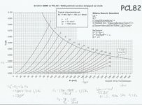
You need to find the parameters of the triode wired 6BM8, at least the u and rp.
Then the distributed capacitance of the choke.
Then the inductance of the output transformer primary.
Then the distributed capacitance of the output transformer primary.
That would be a start.
But the leakage reactance of the output transformer will affect the high frequency response and square waves, at the very least.
And finally, what will be the load on the 600 Ohm output, including the shielded cable capacitance to the power amp input, and its impedance (resistance and capacitance).
I hope someone will chime in with their experience with the output transformer, and with the tube in triode wired mode.
Thank you.
Some of those data is already available:
Rp:1500 Ohms, u=7 (of PCL82)
Distributed capacitance of the choke: Lundahl has no values for this, don't know how to measure without a component tester for chokes
S217D, primary inductance: 38.1H
S217D, distributed capacitance: can't find them in the datasheet of Cine Mag, but they measured a lot of parameters.
600 Ohm preout will feed a 600 Ohm input via shielded XLR microphone cable.
Attachments

Last edited:
I wonder what this topology of a famous tube parafeed output stage makes any sense?
It is a combination of an ordinary cathode follower output stage and an anode loaded tube, maybe a phase splitter combination with equal loads on cathode and anode or just cathode follower circuit combined with a plate loaded tube.
It is a combination of an ordinary cathode follower output stage and an anode loaded tube, maybe a phase splitter combination with equal loads on cathode and anode or just cathode follower circuit combined with a plate loaded tube.
Attachments
Schmitz77,
No DC connection to the Screen?
No DC connection to the Suppressor Grid (or Beam Formers for a Beam Power tube)?
Please build it, and please give us a report of its performance.
I do not believe that circuit will work either reliably, nor repeatably.
You may want to have this moved to become a new thread.
It could become either the shortest thread, or the longest thread.
Just my opinion.
For about 10 years at my work, I had access to a $50,000 Vector Network Analyzer (VNA) plus $$$ Accessories, and $$$ Precision Calibration kits.
It covered from 10Hz to 4 GHz. The return loss bridge for low frequencies was quite simple.
The powerful calculative software and wide dynamic range could make all those measurements (like inductance, distributed capacitance, etc.)
Without that, I still make many of those measurements.
It takes a signal generator, some resistors, a scope, several measurement setups, and a lot of calculations. Then I have to do additional measurements/calculations that are at different setups to confirm the results of the first measurements/calculations.
I do that for chokes, SE and PP interstage transformers, SE and PP output transformers.
The experience with making those measurements on the VNA, I worked out test routines that I can do at home with more simple and less expensive equipment (to a lesser accuracy, less easy measurement setups, and lesser dynamic range).
Accuracy is not that important. Is it 25 H? or is it 27H? That is accurate enough for most applications.
If the manufacturer of chokes and output transformers will not give you a complete set of specifications, then you have to measure for yourself.
Otherwise, you have no way to make a prediction of the performance of a vacuum tube circuit that incorporates those parts.
Last edited:
Schmitz77,
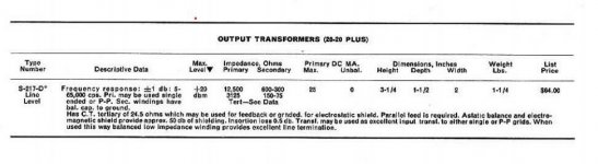
That is a nice transformer specification sheet.
But there is no listing of distributed capacitance, would have been nice.
And I am concerned about 2 other of the specs they do list:
1. The performance is with a 600 Ohm driving impedance.
2. The performance is listed at 0dBu.
0 dBu is 0.775V.
That is not enough for many headphones.
At least it does say the maximum output is 20dBm (into 600 Ohms).
However, with the bad impedance match of a 600 Ohm secondary into a 32 Ohm load, the power will be very low.
Also, an XLR cable of unknown length is an unknown capacitance. What is the length of the cable, and what is the pF/ft of that cable?
Last edited:
Schmitz77,
No DC connection to the Screen?
No DC connection to the Suppressor Grid (or Beam Formers for a Beam Power tube)?
Please build it, and please give us a report of its performance.
I do not believe that circuit will work either reliably, nor repeatably.
You may want to have this moved to become a new thread.
It could become either the shortest thread, or the longest thread.
Just my opinion.
I'll build a parafeed pre soon and will experiment with it, but this is, for now, what could be reverse- engineered from different pics of two tube preamps which have some cult- following. I know that the connections for using a pentode in triode mode is not only one option, but several and that those pseudo triode connections could be discussed controversal, but thats what I can spot on the pics. It mustn't be therefore the last word and can include a mistake in reverse- engineering, too. But its kind ob obscure and against the rules of thumb what I did see there. But its just not the most important part of the circuit, how and where g2 and g3 are being connected to. To me, the whole ensemble looks kind of strange circuit building.
Last edited:
Schmitz77,
That is a nice transformer specification sheet.
But there is no listing of distributed capacitance, would have been nice.
And I am concerned about 2 other of the specs they do list:
1. The performance is with a 600 Ohm driving impedance.
2. The performance is listed at 0dBu.
0 dBu is 0.775V.
That is not enough for many headphones.
At least it does say the maximum output is 20dBm (into 600 Ohms).
However, with the bad impedance match of a 600 Ohm secondary into a 32 Ohm load, the power will be very low.
Also, an XLR cable of unknown length is an unknown capacitance. What is the length of the cable, and what is the pF/ft of that cable?
Hello,
you may get confused here, this isn't an output schemo for driving a 32 Ohm headphone load, this is just a 600 Ohm output for a tube preamp driving a 600 Ohm input load of my tube power amps. Its the old studio standard for signal transmission of 600 Ohm that I use.
Peerless S-217D was the PP- output of the famous Pultec EQP1-A tube equalizer, which has been rebuild by CineMag. It could be used for a parafeed output, too. So the 20dBm should be enough for driving a high- input efficiency power amp (it has input attenuators anyway).
Hope this helps.
Attachments
Last edited:
There is a famous amplifier out there that uses the EL34 Pentode.
It has a separate connection for the Suppressor Grid.
The famous amplifier just connects the Suppressor Grid to a capacitor.
I do not remember where the other end of the capacitor connects to.
The point of that circuit is to isolate the Suppressor grid from any DC voltage, and allow the DC level to float, but to have an AC level that changes with signal (according to the AC voltage that the other end of the series capacitor connects to).
Of course, if the other end of the capacitor connects to ground, then there is no AC signal to the Suppressor grid.
Almost all Pentodes and almost all Beam Power tubes will perform unpredictably if the Screen is left to float to any undetermined DCV level.
For most of those tubes, the tube will not conduct current, unless there is a fairly large level of DC on the Screen.
Beam Power tubes almost always have the Beam Formers connected to the cathode, by an internal connection inside the tube.
Last edited:
Correct.
+20 dBu would be 7.75V.
That should be enough signal for most power amp input connectors.
Yes, I do get confused, you and I both are on at least 2 different threads,
and some of the circuits are slightly similar.
+20 dBu would be 7.75V.
That should be enough signal for most power amp input connectors.
Yes, I do get confused, you and I both are on at least 2 different threads,
and some of the circuits are slightly similar.
Last edited:
Wow, I can only dream about those measurement options.For about 10 years at my work, I had access to a $50,000 Vector Network Analyzer (VNA) plus $$$ Accessories, and $$$ Precision Calibration kits.
It covered from 10Hz to 4 GHz. The return loss bridge for low frequencies was quite simple.
The powerful calculative software and wide dynamic range could make all those measurements (like inductance, distributed capacitance, etc.)
Without that, I still make many of those measurements.
It takes a signal generator, some resistors, a scope, several measurement setups, and a lot of calculations. Then I have to do additional measurements/calculations that are at different setups to confirm the results of the first measurements/calculations.
I do that for chokes, SE and PP interstage transformers, SE and PP output transformers.
The experience with making those measurements on the VNA, I worked out test routines that I can do at home with more simple and less expensive equipment (to a lesser accuracy, less easy measurement setups, and lesser dynamic range).
Accuracy is not that important. Is it 25 H? or is it 27H? That is accurate enough for most applications.
If the manufacturer of chokes and output transformers will not give you a complete set of specifications, then you have to measure for yourself.
Otherwise, you have no way to make a prediction of the performance of a vacuum tube circuit that incorporates those parts.
Just have a scope, some analog and digital multimeters and voltmeters, some signal sources and measures for adjusting R2R decks.
At first, to clarify whats the best working parafeed output circuit option would help me to make a decision what to build.
On one hand, I think an anode choke loaded tube has many advantages, but at the same time I saw this strange resistor output stage and I think, well, this could work out in some way or the other, too. Maybe even betters the choke loaded anode tube schemo. But maybe I'm wrong.
In the end, I could build only circuits that are safe and sure to operate excellent. I can change some values of the circuit, but don't do breadbord style circuits with months of variations on concepts in reality. The theoretical concept of an amp has to be established before building, because I'm not flexible enough to make big changes in parts and circuits afterwards.
Last edited:
There is a famous amplifier out there that uses the EL34 Pentode.
It has a separate connection for the Suppressor Grid.
The famous amplifier just connects the Suppressor Grid to a capacitor.
I do not remember where the other end of the capacitor connects to.
The point of that circuit is to isolate the Suppressor grid from any DC voltage, and allow the DC level to float, but to have an AC level that changes with signal (according to the AC voltage that the other end of the series capacitor connects to).
Of course, if the other end of the capacitor connects to ground, then there is no AC signal to the Suppressor grid.
Almost all Pentodes and almost all Beam Power tubes will perform unpredictably if the Screen is left to float to any undetermined DCV level.
For most of those tubes, the tube will not conduct current, unless there is a fairly large level of DC on the Screen.
Beam Power tubes almost always have the Beam Formers connected to the cathode, by an internal connection inside the tube.
OK, understood. Well, this could be a reason why to use a small foil cap for connection of those grid. Someone must have done some deeper thoughts on this theme here.
Correct.
+20 dBu would be 7.75V.
That should be enough signal for most power amp input connectors.
Yes, I do get confused, you and I both are on at least 2 different threads,
and some of the circuits are slightly similar.
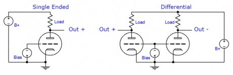
When reviewing this pre, Art Dudley wrote:
[FONT=Times New Roman, serif]"The C3m is also capable of very high gain, but Ken Shindo puts it to a different sort of use: In the Vosne-Romanee, the Siemens tube functions as a resistance-coupled phase inverter, the output of which appears across the anode and the cathode"
[/FONT]
[FONT=Times New Roman, serif]And what could be seen are two resistors at the cathode and at the anode of the tube, so what we have here should be a classic phase inverter. But will this work with a single ended parafeed wired transformer? One signal negative, one positive, and without equal values like in a phase inverter?[/FONT]
[FONT=Times New Roman, serif]I mean, WE did nearly the same in the WE 92A. So my question will be: will this circuit work with unequal resistors in anode and cathode and the S217D being used as single ended wired parafeed transformer? And will it provide better results compared to a simple, anode choke loaded tube output, using the same transformer, parafeed wired? Comparing both, which is preferable and why?
[/FONT]
[FONT=Times New Roman, serif]
[/FONT]
Attachments
Last edited:
You can determine choke's capacitance by doing frequency sweep of choke's impedance. Choke's Q factor (the ratio of impedance to DCR) has a frequency peak at which inductive and capacitive impedances are approximately equal. Don't expect miracles though. A typical 50-100 H audio choke has impedance peak below 1000 Hz. At frequencies above impedance peak, such choke becomes a capacitor.
I would just add another tube and make a differential stage with your transformer.
I would just add another tube and make a differential stage with your transformer.
I am pretty sure that I am running out of time and energy.
I am not going to design circuits all the time, especially when the exact requirements are not known.
Many who are less experienced do not know the exact requirements, I expect that.
I have worked around 600 Ohm stuff, but never ever built anything for it.
Actual input and Actual output impedances (600 Ohm loaded and 600 Ohm unloaded),
Actual voltages out, loaded and unloaded, from the signal source, Actual voltage input requirements of the amp that follows the preamp, with 600 ohm termination, and without termination at the power amp input, are needed to be known.
Requirements like frequency response, and square wave response are needed too.
A transformer output that is loaded with 600 Ohms, and that same transformer that is not loaded, will give entirely different performance (gain, max voltage, frequency response, square wave response, distortion, etc.).
An unknown target will never be hit.
Those who are more familiar with 600 Ohms will be better qualified than me.
Part of the problems with 600 Ohm systems, is that they all used to be 600 Ohms in, and 600 Ohms out, and usually used transformers for the common mode rejection they provided. When they used one signal source and 2 loads, one solution was to have one provide 60 Ohms load, and the other provide a very high impedance.
Over the decades, some transformers went away, some used only high impedance loads, some double terminated . . . etc.
In time, the Standard, became Non Standard.
I worked with RF all the way from 2 MHz to 40 GHz in coax, and all the way to 500 GHz in waveguide. Keeping the systems meeting the standards for impedance in those systems is paramount, they are very well controlled. Otherwise it will not work, or not work predictably.
Unfortunatey, 600 Ohm systems have been working unpredictably because there is no adherence to a "Standard" anymore.
Last edited:
Many thanks. Do you think a good, conventional output transformer would have better data compared with a good anode choke when it comes to bandwith and resonance peaking?
I think what we have in the WE 92A circuit is a kind of differential output with one tube.
I think what we have in the WE 92A circuit is a kind of differential output with one tube.
Attachments
OK, thanks a lot for your patience and participation. It helped a lot to clarify!I am pretty sure that I am running out of time and energy.
I am not going to design circuits all the time, especially when the exact requirements are not known.
Many who are less experienced do not know the exact requirements, I expect that.
I have worked around 600 Ohm stuff, but never ever built anything for it.
Actual input and Actual output impedances (600 Ohm loaded and 600 Ohm unloaded),
Actual voltages out, loaded and unloaded, from the signal source, Actual voltage input requirements of the amp that follows the preamp, with 600 ohm termination, and without termination at the power amp input, are needed to be known.
Requirements like frequency response, and square wave response are needed too.
A transformer output that is loaded with 600 Ohms, and that same transformer that is not loaded, will give entirely different performance (gain, max voltage, frequency response, square wave response, distortion, etc.).
An unknown target will never be hit.
Those who are more familiar with 600 Ohms will be better qualified than me.
- Home
- Amplifiers
- Tubes / Valves
- 6BM8/ECL82 parafeed line output