Hi guys,
Does someone has the service manual or the electronic scheme of the Excursion HXA5K / Soundmagus X3500?
Thanks!!
Maxikill97
Does someone has the service manual or the electronic scheme of the Excursion HXA5K / Soundmagus X3500?
Thanks!!
Maxikill97
If no one has anything specifically for that amp, post a good quality photo of the component side of the entire main board and the component side of any driver boards.
I have 2 broken SoundMagus X3500 amps.
I will first describe the amplifier with most of the damage.
One amplifier had a completely blown up power supply.
All fets were cooked and all the 12 power supply drive transistors were blown too (marking 2X and 2T)
There is a sawtooth wave present on the TL494, but it just doesn't produce any PWM output. The TL494 stays in protect (pin 3 of the TL494 is high, +4.4v).
The power LED is blinking and the alarm LED stay's red.
The power supply fets are not installed in this stage.
For the second amp, start a new thread.
Photos may help others if you can post them.
Did you see the note about FETs being in the circuit in the following post:
Massive D8000
Photos may help others if you can post them.
Did you see the note about FETs being in the circuit in the following post:
Massive D8000
I fit 1 fet per bank. Now the PWM was generated.
All the power supply fets worked properly and had a nice clean output PWM wave, it pulled 1.60a in total at idle(with the output fets installed), but after a couple seconds it randomly started to pull more amps and it went in protect (none of the fets were hot).
I removed the output fets because there were some shorted ones in between (strange, couldn't remember there were bad fets in, but ok), and the output fets had a very nice clean sine PWM on the gate resistors of the IRF640n.
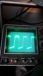
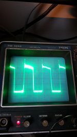
At this stage the 2 mosfets (push and pull bank) from the middle power supply transformers had strange output PWM from the mosfets (please watch the attached photo)
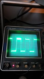
One pull bank has a rising edge at the bottom, and the other push bank has a rising edge at the top. All the other 4 banks from the other 2 transformers has a very clean output PWM.
Any idea's?
All the power supply fets worked properly and had a nice clean output PWM wave, it pulled 1.60a in total at idle(with the output fets installed), but after a couple seconds it randomly started to pull more amps and it went in protect (none of the fets were hot).
I removed the output fets because there were some shorted ones in between (strange, couldn't remember there were bad fets in, but ok), and the output fets had a very nice clean sine PWM on the gate resistors of the IRF640n.
At this stage the 2 mosfets (push and pull bank) from the middle power supply transformers had strange output PWM from the mosfets (please watch the attached photo)
One pull bank has a rising edge at the bottom, and the other push bank has a rising edge at the top. All the other 4 banks from the other 2 transformers has a very clean output PWM.
Any idea's?
Attachments
You need to compare the gate drive on the gate leg of the FETs between the good and bad transformers to see if there is a difference.
There is no difference in gate drive.
They are the same on all 6 banks.
I replaced all gate resistors, drive transistors, TL494
About the previous photos:
Photo 3 is from the 4 other good banks. That fets stay nice and cold.
The fets from photo 1 and 2 get slowly hot which belong to the middle transformer
They are the same on all 6 banks.
I replaced all gate resistors, drive transistors, TL494
About the previous photos:
Photo 3 is from the 4 other good banks. That fets stay nice and cold.
The fets from photo 1 and 2 get slowly hot which belong to the middle transformer
Last edited:
Twisting and wiggling the transformer does not make a difference unfortunately.
It is very strange. To make sure the pwm drive was okay, I changed the gate drive transistors from both bad banks and I fit some new fets again.
Now it is making a constant ticking noise from about 5Hz, and it does not create a sine wave (amplifier in protect). The fet from 1 bank from the bad transformer heats up much more quickly (the other fet from the bad transformer does not heath up more quickly).
Seems like it tries to power it up and then it shuts off again, with a frequency from about 5 Hz.
I don't get it why it behaves like this.
Do you have any idea's?
By 'sine wave' are you referring to the square wave produced by the PS FETs?
If you leave the FETs out of the bad transformer, will the other 2 power supplies function normally?
If you leave the FETs out of the bad transformer, will the other 2 power supplies function normally?
It seems a broken transformer, do you have a inductance meter to measure te windings? If I have issues with power supplies like this, i remove the dual-diodes for the railvoltage also.
I checked, the windings were OK, no strange reading on the inductance meter.
I changed all the gate drive transistors again. Now it works properly. All square waves on all fets (power supply and output section) are very clean and they stay cool.
The idle current is 1.3a on 10.9v. Maybe a bad batch of 2x and 2t transistors???
Now the next problem occured.
The amplifier starts up perfectly at 10.9v with perfect looking square waves.
When I crank the voltage up to 13.2v it gives a little ticking sound somewhere on the power supply. Then it shuts off again.
When I have the amplifier operational at 10.9v, and I wiggle on the transformer to check for any short circuits, nothing happens. It stays operational.
Higher the voltage to 13.2v+ and it shuts off again
See if there is any pulsing on any of the PS ICs or driver board header that coincides with the ticking?
I checked.
It seems like it gets triggered by PIN 16 of the TL494 IC.
<12v PS voltage, it seems to be connected to GND (a voltage of 0.02V).
>12V PS voltage, it seems to rise quickly
12.3V PS voltage, the voltage on PIN 16 is 0.12v
12.6V PS voltage, the voltage on PIN 16 is 0.5V
12.8V PS voltage, the voltage on PIN 16 is 1.15V
12.9V PS voltage, the voltage on PIN 16 is 1.60V
13V PS voltage, the amplifier shoots into protect, pin 16 stays at a steady 4V.
Pin 15 is always 2.05V
This seems to be the only pin which is reacting to the protection mode.
Do you have an LM393 in the power supply area?
Do you see a group of transistors designated as Q85, Q86 and Q87?
If so, does the collector of Q87 connect to pin 16?
Does this amp have any of the brown fixative anywhere?
Do you see a group of transistors designated as Q85, Q86 and Q87?
If so, does the collector of Q87 connect to pin 16?
Does this amp have any of the brown fixative anywhere?
Yes, there are 2x 393 chips in the power supply.
Pin 16 is connected to the collector of transistor Q14 (marking 2T).
There also was brown fixative on the power supply and after removing that it did not went in protect when the PS voltage was 14.4v (pin 16 of the TL494 was grounded).
When hooking a load onto the amplifier, no matter if it's 1, 2 or 4 ohm, it always shoots into protect and you hear the same little thick (pin 16 of the TL494 is again steady at 4v).
Currently it does again shoot in protect when the voltage is >13v or when load is connected. Seems like pin 16 from the TL494 is always the causing here.
Because it shoots into protect when connecting a load I suspect it could be something on the output section which is causing this strange problem.

- Home
- General Interest
- Car Audio
- Service manual Excursion HXA5k / Soundmagus X3500