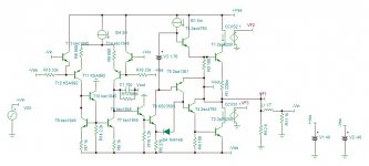
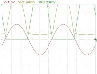
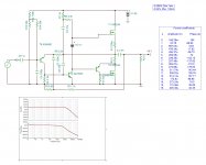
At first glance the output looks to be quasi complimentary but it isn't. The diode feedback is a game changer in this story, as the scope graph shows the upper output never cuts off.

At this stage it is in open loop with a gain of 60db 20khz F3 with a distortion of 0.13% at 30Vp 10khz, and decreases with lower powers keeping even order dominant.
Hayk
At this stage it is in open loop with a gain of 60db 20khz F3 with a distortion of 0.13% at 30Vp 10khz, and decreases with lower powers keeping even order dominant.
Hayk
Attachments
Add a 1k resistor to the T61 emitter. Connect the emitter of the T61 to the base of the T65 Through a diode..
Class A + C? Like GM.
Class A + C? Like GM.
Last edited:
I did simulate the model. First I was astonished to find exactly the measured distortion given on the manual to be 0.075% 1khz up to 8w. I reduced sensitivity with higher NFB and I got THD down to 0.01% and f3 1.5Mhz. I applied your proposition, the distortion became 0.4% however the f3 doubled.
Hayk
Hayk
Attachments

Last edited:
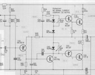
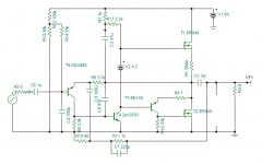
Remake NFB as JLH1969. Short-circuit D1,D4. Decrease R6,7.2-3 times.Remove 330m.Reduce R4 47ohm..🙂
Last edited:
I modernized the Dual cv30. It is no more quasi complimentary, I don't know how it is to be called. Due to non symmetric character, it has even order dominant distortion. However, it is 40w instead of 10 and 0.006% instead of 0.07% at 1khz. It is biased 9ma instead of 20ma.
Hayk

Hayk
Attachments
Quadrupling the output power might have been expected as you almost doubled the supply voltage 😉.
Best regards!
Best regards!
The original with 60v supply, yes I quadruple the power but the distortion at 35w is 0.26% instead of 0.006% with the mosfets.
By the way, the upper mosfet needs a gate stopper of 50 ohms for best square wave.
By the way, the upper mosfet needs a gate stopper of 50 ohms for best square wave.
Last edited:
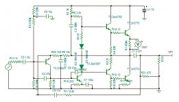
The maximum is 60v for irfz44 but there is 4v drop out on negative rail , can also be on positive with a ccs which halves the distortion.
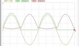
I wonder if there is something wrong or a miracle going on in this circuit. I forgot to check the bias with these new mosfets. There is only 200ua bias the bd is cut off but there is no any crossover distortion. On the contrary , when I apply some bias of 15ma, the distortion increases!
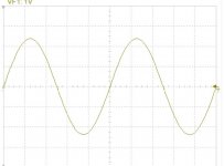
This is the 10khz output V/I biased.

This is the 10khz output with 0 volt bias .

This is with 3.5v bias with 0.28ma.

Lowest distortion is with bias voltage of 4.2v with 0.28ma (leakage current?). How is this possible?
This is the 10khz output with 0 volt bias .
This is with 3.5v bias with 0.28ma.
Lowest distortion is with bias voltage of 4.2v with 0.28ma (leakage current?). How is this possible?
Attachments


Last edited:
So what is the secret sauce? You mention "diode feedback".
In post 1, D4 cathode goes to the base of a lower emitter follower driver.
In post 7 D4 anode goes to the collector of the shizai driver.
In post 9 & following there is no d4 at all? changing to mosfet outs doesn't help understanding much.
I'm interested because the dual cv30 has the topography of the Apex AX6, which I have built. It sounds very good, but getting from .06% hd someone quoted for ax6 to .00x% might not be audible on my speaker, but what is the secret, adding 1 diode?
Indianajo, thank you informing me about apex AX6, I will have a look. As you see on the first scope graph, with mosfets, the upper output remains conducting without diode. The problem that annoying me, without bias in class B, it has lower distortion. This means there is still work to be done.
- Home
- Amplifiers
- Solid State
- Semi Non-Switching Output Stage of LM3886 Clone