I'm looking to supplement my new build with a phono preamp as the next step, specifically for RIAA adjustments. I wouldn't mind building a kit, but so many of the ones I run into use op amps or mosfets in the signal line. Merlin sells a PCB on his site:
The Valve Wizard
Has anyone tried this or have any strong opinions about it?
I'm in the US if that makes a difference as far as sourcing.
The Valve Wizard
Has anyone tried this or have any strong opinions about it?
I'm in the US if that makes a difference as far as sourcing.
Last edited:
I'm looking to supplement my new build with a phono preamp as the next step, specifically for RIAA adjustments. I wouldn't mind building a kit, but so many of the ones I run into use op amps or mosfets in the signal line. Merlin sells a PCB on his site:
The Valve Wizard
Has anyone tried this or have any strong opinions about it?
I'm in the US if that makes a difference as far as sourcing.
I have built one of these, i also used a spectrum analyzer to test it :
Merlin 3-tube RIAA
I have built one of these, i also used a spectrum analyzer to test it :
Merlin 3-tube RIAA
So, in your opinion, totally worth it? With no band on the axis, it's hard to tell what I'm actually looking at.
You are looking at a spectra , 1 khz is the big peak, 2khz second overtoneSo, in your opinion, totally worth it? With no band on the axis, it's hard to tell what I'm actually looking at.
is seen app. 68dB. Third and forths may be guessed below 80dB.
Input 3.7mV output 1Volt. THD = 0.06%
You are looking at a spectra , 1 khz is the big peak, 2khz second overtone
is seen app. 68dB. Third and forths may be guessed below 80dB.
Input 3.7mV output 1Volt. THD = 0.06%
Sorry, there was no scale or labels on that axis so I didn't want to assume anything.
Sorry, there was no scale or labels on that axis so I didn't want to assume anything.
My analyzer hp 3580A does not produce scales, it only plots on an XY plotter.
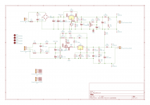
The merlin board is very flexible, i built the variant with ECC83 + ECC82
and "all in one" eq.
I also skipped the electrolytics at the output and it's accompanying
protection circuits.
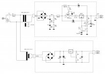
I used another of Merlin's boards - a Maida regulator for B+ and DC heaters. I ended up recreating his PCB and have a few available if anyone is interested. Although a thread in the Power Supplies forum seems to have noticed an issue with the background design. I'm no expert or audiophile - works fine for me.
Attachments
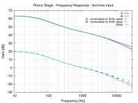
Here is my version with hi-gm triodes 6S3P-EV. These produce some 6...7 dB better signal to noise ratio compared to typical 12AX7/ECC83 constructions.
Gain is 40,3 dB, noise level at the input is 0,75 µV when terminated with 50 ohms.
THD = 0.08 % at 1 Vrms out.
Gain is 40,3 dB, noise level at the input is 0,75 µV when terminated with 50 ohms.
THD = 0.08 % at 1 Vrms out.
Attachments

Standard the termination at the input for MM is 600 ohm ( I believe is an international rule, not sure).
Then the input capacitance of 6S3 is 6,9 pF, I think is great; if you reach the max gain of 50 the input capacitance is not so low.
Also, for the second stage it is in parallel with other caps of riaa.
Do you have a freq. response ?
Last the comparision on 12AX7 must be done with same gain so you can get the value of input noise reading the output noise / gain, with 22-22kH bw and weighted A , as international rules.
Of course it seems to be lower as noise than 83 but there is also the contrbute of power supply and his level of ripple.
Walter
Yes, typical MM-cartridge model consist of some 500 ohms in series with some 250 mH inductance.
The termination resistance was 50 ohms when I compared this 6S3P-EV RIAA with my earlier 6N2P-EV. I think the difference of the results is most essential.
Measured input capacitance was 95 pF.
Frequency response of this particular sample was +0...-0,38 dB vs. RIAA curve,
but ofcourse the response depends on the accuracy of used R and C components.
The gain of compared RIAAs need not to be the same. I gave my result as input noise.
This requires that one can make some basic arithmetics.
The audio filtering I used for noise measurement was HP 300 Hz...LP 20 kHz (due to analyzer's options)
May i ask what your noise figures is at the line-out side ?
Expressed as mV ( p-p or RMS whatever is easiest) with the input shorted.
( yes you already told us about input noise and 40dB , but i am to
inexperienced to try to convert this)
Expressed as mV ( p-p or RMS whatever is easiest) with the input shorted.
( yes you already told us about input noise and 40dB , but i am to
inexperienced to try to convert this)
The output noise is what was actually measured, and the result at the output was 75 µV (RMS).
Since the gain of the RIAA was 40,3 dB (A=103), the noise at input is 75 µV/A = 0.73 µV.
Actually this reading (noise at input) is affected by RIAA-filtering and is not therefore fully "real" but makes possible to compare noise levels of different RIAA-amplifiers.
Since the gain of the RIAA was 40,3 dB (A=103), the noise at input is 75 µV/A = 0.73 µV.
Actually this reading (noise at input) is affected by RIAA-filtering and is not therefore fully "real" but makes possible to compare noise levels of different RIAA-amplifiers.
Take a look at the Bottlehead Reduction and Eros 2 kits. The kits come with almost moron proof step by step assembly instructions.
In which way you have measured 95 pF?
For the s/n the method you use is not compliant with standard.
Regarding the s/n it is evident that riaa eq can help for High frequency but the topology of thi circuit make difference.
In my opinion the low Z of riaa eq, in a passive circuit, is the way to follow
Walter
For the s/n the method you use is not compliant with standard.
Regarding the s/n it is evident that riaa eq can help for High frequency but the topology of thi circuit make difference.
In my opinion the low Z of riaa eq, in a passive circuit, is the way to follow
Walter
Thanks for the explanation.The output noise is what was actually measured, and the result at the output was 75 µV (RMS).
Since the gain of the RIAA was 40,3 dB (A=103), the noise at input is 75 µV/A = 0.73 µV.
Actually this reading (noise at input) is affected by RIAA-filtering and is not therefore fully "real" but makes possible to compare noise levels of different RIAA-amplifiers.
The input capacitance was measured by inserting a series resistor at the gate of first 6S3P-EV so forming a RC and then measuring -3 dB point of frequency response.
The rest is again plain arithmetics.
In theory the input capacitance should be some 75 pF, but the PCB, layout, tube socket etc. seem to have the effect of some 20 pF.
The calculation is based on the following: According to tube data of 6S3P-EV: Cgk = 6,9 pF + 1 pF; Cga = 2,2pF.
The gain of first stage is 29.8 dB (A = 30.8)
There are different standards, but this is not relevant in this case. My purpose was to find out the possible difference of noise generated by 6S3P-EV and 6N2P-EV.
I found out that 6S3P-EV generated 6.6 dB lower noise than 6N2P-EV. This was releveant to me.
The rest is again plain arithmetics.
In theory the input capacitance should be some 75 pF, but the PCB, layout, tube socket etc. seem to have the effect of some 20 pF.
The calculation is based on the following: According to tube data of 6S3P-EV: Cgk = 6,9 pF + 1 pF; Cga = 2,2pF.
The gain of first stage is 29.8 dB (A = 30.8)
For the s/n the method you use is not compliant with standard.
There are different standards, but this is not relevant in this case. My purpose was to find out the possible difference of noise generated by 6S3P-EV and 6N2P-EV.
I found out that 6S3P-EV generated 6.6 dB lower noise than 6N2P-EV. This was releveant to me.
Last edited:
The input capacitance is listed 6,9 pF for 6S3P.
As data sheet.
https://bms.isjtr.ro/sheets/112/6/6S3PEV.pdf
PS: a little doubt about the indication of input capacitance, I assume it is Cag.
In my opinion is always better to use a low Z riaa network to get the best results in addition, of course, with a high gm a low Rp tubes ( with a good gain.)
To measure capacitance we use a tre way rotary switch to select the appropriate value of cap, this box is connected in series with input and the frequency is 20 kHz.
We we read the half value on input terminal we got the real value of Cin
For MM the Vin is set at 5 mV, then we set with AP the 0dB for the output voltage, put a 600 ohm termination on input , 22-22 kHz filter and weighted B.
These are standard measurement
With 83+88 and 41,7 dB of gain I got 78dB, good.
With 5965+88, 41 dB gain, found 81 dB also good
with 7062+88, 42,6 gain, found 80dB
In my circuit there is the possibility with two jumper to select between four different gain without any changes on performances.
Due the topology the higher gain introduce a little changes on s/n
Walter
Last edited:
- Home
- Amplifiers
- Tubes / Valves
- Pure tube phono preamp kit