I have a couple of LJM L12-2 that I would like to play around with, and try EF output stage instead of CFP.
I don't have the spice model for the 12-2, so I used one I found for the MX50SE, which is very similar, but only has one output pair.
Basic simulation seems ok, but before going ahead and soldering, I thought I would check with the experts 🙂
There are two things that I have been thinking about:
-compensation/stability, should probably be re-tuned?
-Current through drivers seems to give little chance in distortion FFT. What would be general advice/considerations for choosing the resistor between drivers?
Attachments
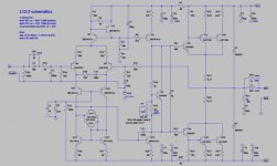
Output stage CFP to EF...
CFP has the order of the transfer function +1. This will require a change in correction to ensure stability.
Output transistors with a higher cutoff frequency are needed.
CFP has the order of the transfer function +1. This will require a change in correction to ensure stability.
Output transistors with a higher cutoff frequency are needed.
Since I don't know how to simulate stability of the circuit (pole/zero/OLG etc), and don't have the correct model for the 12-2, all I can do is check stability on scope. I'm thinking no load, 8ohm & 4ohm, and with a small cap on the output.
I think the outputs used should be very fast (SA1186 / SC2837), so finding even faster ones is not 'in the scope' 🙂 Only use the ones I have.
These boards have been left unused since I did not like the sound much(even if they measured fine), so I just thought I would play around with them and see if I can make them more pleasing to my ears.. Very basic level here..
And I also plan to mount the 'bias compensation transistor' thermally coupled to the outputs, and not the drivers as it is now.
Last edited:
Since I don't know how to simulate stability of the circuit (pole/zero/OLG etc)
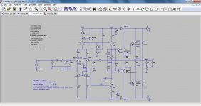
Share your *.spice file, i will add necessary components and settings.
Thank you! I ran the sim, and it seems to work (same result as you posted)
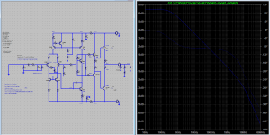
Forgive me for being a novice, but if I'm reading this correctly, phase is around 90deg where OL gain is 0? This should make a stable amp right?
Forgive me for being a novice, but if I'm reading this correctly, phase is around 90deg where OL gain is 0? This should make a stable amp right?
Thank you! I ran the sim, and it seems to work (same result as you posted)
Pretty fine! Save this sheet with _OLG appendix.
Forgive me for being a novice, but if I'm reading this correctly, phase is around 90deg where OL gain is 0? This should make a stable amp right?
Clearly!
Comment .step directive with ; in front, put voltage signal source at the now grounded input and use .tran instead of .ac.
Save modified sheet with _TRAN appendix.
I have some trouble with the bias adjustment, have to check that.. Current gets too high when I increase voltage, can't adjust it low enough even if trimpot is set to 0..
I got one modified board up and running. Only running one output pair at the moment and low output power (which I think is more significant). I tried 120 and 75 ohms as emitter resistor for the drivers, and there was a big difference in what Iq was needed to get good distortion. I did not see such a difference in the simulation. Now the Iq is around 50mA. Seems stable too. I get ringing with a cap across the output and square wave in, but it's damped. No LR on output.
Looks promising I think.
EDIT: broke a lead to the load resistor while replacing the emitter resistor to the drivers, so now I need to up the Iq again to get low distortion.
Looks promising I think.
EDIT: broke a lead to the load resistor while replacing the emitter resistor to the drivers, so now I need to up the Iq again to get low distortion.
Attachments
Last edited:
I tried double output pairs now, and then it is no longer stable with a 470p cap across the output (stable with LR though). Should I worry about that, or should I try something to make it more stable?
How about base resistors for the outputs, would they help? Or what is really their purpose? I see OLG falling quite early (?) in the simulation, so increasing compensation cap value would probably be bad for distortion?
How about base resistors for the outputs, would they help? Or what is really their purpose? I see OLG falling quite early (?) in the simulation, so increasing compensation cap value would probably be bad for distortion?
Due to some badly marked supply leads, one board went up in smoke. I measured the one still working, and performance was mediocre, and required a lot of Iq to achieve even that. On the positive side, the distortion had a falling spectrum with high Iq.
I never had a chance to listen to them before the smoke escaped from one of them.
On stability, I noticed that if I connected the cap directly on the board, it oscillated, but if I connected it over the load resistor, there was no oscillation. Leads to load was only 15cm long.
Now I give up on these, chapter closed.
On stability, I noticed that if I connected the cap directly on the board, it oscillated, but if I connected it over the load resistor, there was no oscillation. Leads to load was only 15cm long.
Not so much amps could survive such a test.
Mostly all will oscillate wildly until a PCB traces naturally burn.
You can easily simulate this on *_OLG.asc sheet.
Actually, most of the amps I have tested were ok with this. Some oscillate mildly, but usually they don't go berserk with full swing oscillation.
I decided to have another look, and found it was only the protection diodes that was destroyed, but they did protect the rest when I reversed the polarity.
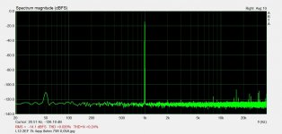
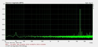
So, I found I needed to run abt 0,45A Iq (30V supply) to get decent distortion spectrum. With lower Iq there was too many high order harmonics for my taste. Now it has 2nd and 3rd at around 80-90dB depending on output power, the higher harmonics are at abt -100dB or so.. I tried a 0,1u cap over the emitter resistors for the drivers, but it did not seem to change the distortion.
I'm now using double output pairs with the std 0,15ohm emitter resistors.
I listened to it, and it did not sound too bad. However, gain is too high feeding it directly from DAC, so I'm thinking I should try to reduce that. Change the feedback resistor? Or could I do something to decrease OLG (and distortion), and increase the OL BW too? That seems like a more appealing solution in my mind..
I'm a novice, so I hope to get some general suggestions on how to approach this?
Last edited:
Your intuition about OLG, OLBW is exact. You must first understand that musical message is in the envelope, not the timbre. The harmonic distortion bellow 0.1% THD, means nothing, as over 100khz Fr. Your amp is a standard 3 stage Miller with 300hz OLBW. All frequencies above reach the initial transient 90° delayed, the feedback that will adjust it, needs an error at the output to do so. This error is similar to crossover underbiased distortion, occurs only at the beginning of the envelope. If it is a single voice/instrument, it is unaudible, but if multiple envelopes start simultaneously as a choral or orchestra, there things go wrong. The recipe for this is to have the OLBW over 20khz.
You have the sublimed JLH that you like the sound, use it as reference to adjust this amp comparatively.
You have the sublimed JLH that you like the sound, use it as reference to adjust this amp comparatively.
Last edited:
The current in R22,R23 is around 6m.A. The driver stage has to run enough current to remove base storage charges in the outputs in order to turn them off on opposite cycles.
This need is covered in an article one of two about TIM on Bob Cordell's website - see http://www.cordellaudio.com/papers/another_view_of_tim.pdf
This need is covered in an article one of two about TIM on Bob Cordell's website - see http://www.cordellaudio.com/papers/another_view_of_tim.pdf
@kokoriantz
I'm sorry, but I don't get all the things you are saying, but some I understand..
I tried playing around with the emitter resistor for the VAS transistor, and could see OLG go down. I also adjusted the feedback resistor to decrease OLG gain, and OLBW increased. However when it comes to stability, it went terribly wrong. I was not able to get anywhere near what I wanted by adjusting the miller cap and the RC on the input stage (between the LTP as I beleive it's called).
I have not done the similar analysis on the sublimed JLH, since I have no clue how to set up the stability simulation, this here was done by BesPav. I'm lost when it comes to compensation.. I started reading in Cordell's book about it, but did not get far until it started frying my brain 🙂 I think I need some time to let it sink in step by step. Not easy to train an old dog..
@mjona
These are actually a total of 150ohms at the moment. I tried 75ohms, but the drivers got a bit warm, and since they are only cooled by the PCB as it is, went with 150. I read something about the base charge somewhere, and that a small cap across the resistor could improve that, but I saw no difference with the cap installed. Maybe I should try a lower resistance..
The Tian plot suggests the amplifier should be stable from the viewpoint of phase and gain margins.
Ideally the drivers and outputs and the vbe sense transistor Q8 would be attached to the heat sink. Does the pcb allow that.
Re stability phase starts to change a decade in frequency below the -3dB point (where gain has reduced to 0.707) so this will reach an angle of -180 degrees before the gain reduces to unity (0dB, value=1) beyond that the phase is no longer negative and becomes positive. At that point a gain of 1 is sufficient to cause a circuit to oscillate.
To get a rough idea on the issues presented consider the hands on a household clock with phase shift represented by the minute hand - this pointing direction in angles.
From a starting point with both clock hands pointing to the sky at 12 the minute hand get to point in the opposite direction (phase) in 30 minutes when this points to 6.
Consider 6 as the point where the hour hand representing gain reaches 0dB.
Last edited:
I listened to it, and it did not sound too bad. However, gain is too high feeding it directly from DAC, so I'm thinking I should try to reduce that. Change the feedback resistor? Or could I do something to decrease OLG (and distortion), and increase the OL BW too?
Heh.
Now you have stepped on yhe long snd greasy road.
On the one hand you have lower distortion due to as high as possible feedback depth in a loop, while contrary on the other hand you have the needed for keep stability margins.
No other ways to went out.
Anyway first you need to pick from your input and VAS stages as much gain as you can. Next you set outer gain of the amp and all excess gain will left in the feedback loop minimizing distortion.
Last you need to use freq-correcting elements to stabilize loop response and provide needed margins at a worst case of load.
All of this will straightly depend on the bandwindness of you output stage. Start from there. OPS pole freq must be placed somewhere at -6-10 dB freq point of the overall feedback loop graph. I.E. you must exclude influence of the OPS to the amplifier stability margins because OPS have much stresses under heavy load and since it's pole freq changes up to 10 times depending of flowing current.
It's better to start from something like this:
The YAP Output Stage
- Home
- Amplifiers
- Solid State
- Output stage CFP to EF on LJM amp?