It doesn't really matter - it's basically only a different overall EQ. I prefer constant acceleration because the raw polars are visually closer to what you see when measuring real devices, so I started and continue to use that. For normalized polar maps it makes absolutely no difference.
I don't actually own any tweeters that I can measure, but if someone sends me a drawing of a tweeter with dimensions I'd be happy to give it a shot. I'd consider it good practice for learning the tools 🙂
Along a similar vein, I'd like to validate the results I'm getting from the 4.6.0 demo1 file - just to make sure I've got things set up properly.
Here's what I get when I simulate the demo1 waveguide (updated to run from 500-20k Hz with 30 steps, normalized to 0 degrees). Could someone else run the same simulation and post the results? Or link me to where they've already been posted? Thanks!
Here's what I get when I simulate the demo1 waveguide (updated to run from 500-20k Hz with 30 steps, normalized to 0 degrees). Could someone else run the same simulation and post the results? Or link me to where they've already been posted? Thanks!
Attachments
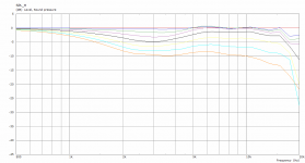
I get the same.
(To get stable results to 20 kHz you would have to set the mesh elements smaller, i.e. decrease the Mesh.*Resolution.)
(To get stable results to 20 kHz you would have to set the mesh elements smaller, i.e. decrease the Mesh.*Resolution.)
Attachments
Last edited:
Great! That's good to hear.
Regarding the mesh resolution, I was wondering about that... How far would you recommend decreasing the value to get valid results out to 20k?
Regarding the mesh resolution, I was wondering about that... How far would you recommend decreasing the value to get valid results out to 20k?
I don't know, I seldom do that, but as this seems to be stable to about 12 kHz, I would try to decrease both Mesh.*Resolution values to 60%. Or maybe first try to set *.InterfaceResolution to the same value as *.ThroatResolution. Be prepared that it will take A LOT more CPU time.
What you could also do is to generate this finer mesh and run the analysis for only a few frequencies (8 to 16?) from 10 kHz to 20 kHz. The curves can be merged in VACS.
No one tried to model some other direct-radiating tweeter yet?
I've been chomping at the bit to try it, but I'm so buried at work it's not even funny
No one tried to model some other direct-radiating tweeter yet?
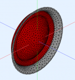
I have a model here that I am planning to put on the 3D printer this weekend.
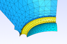
The Source.Contours section includes the first arc of the tweeters chassis, so it looks a bit strange compared with your examples. This way I have a reference to the front of the tweeter chassis. The WG profile starts at a bit smaller diameter, to get closer to the surround.
I have also increased mesh size of the source, compared with your example. Computing time is about 20 minutes now. Is this too course, you think?
There is some irregularities in the simulation between 15 and 20 kHz, but I think it is good enough to make a model and measure it to check how this correlates.
Code:
Throat.Profile = 1
Throat.Diameter = 34.0		; [mm]
Throat.Angle = 40 		; [deg]
Coverage.Angle = 45
Length = 52

Geometry.Definition = 1

Term.s = 0.7
Term.n = 4.0
Term.q = 0.995

Source.Contours = {
zoff -2

point p1 5.2 0 2
point p2 0 13.83 1
point p3 1.75 15.58 1
point p4 0 17.33 1
point p5 4 20.35 2
point p6 4 19.35 2
point p7 3 18.0 2

cpoint c1 -15.8 0
cpoint c2 0 15.58
cpoint c3 0.435 21

arc p1 c1 p2 1.0
arc p2 c2 p3 0.75
arc p3 c2 p4 0.25
arc p4 c3 p5 0
line p5 p6 0
line p6 p7 0
line p7 WG0 0
}


Morph.TargetShape = 1
Morph.FixedPart = 0.0
Morph.Rate = 3
Morph.CornerRadius = 35 ; [mm]
Morph.TargetWidth = 202.0
Morph.TargetHeight = 162.0
Morph.AllowShrinkage = 1

; -------------------------------------------------------
; Mesh Setting
; -------------------------------------------------------

; ABEC
Mesh.AngularSegments = 64
Mesh.LengthSegments = 20
Mesh.CornerSegments = 8

Mesh.ThroatResolution = 4.0 ; [mm]
Mesh.InterfaceResolution = 8.0 ; [mm]
Mesh.InterfaceOffset = 5.0 ; [mm]

; -------------------------------------------------------
; ABEC Project Setting
; -------------------------------------------------------

ABEC.SimType = 1
ABEC.f1 = 1000 ; [Hz]
ABEC.f2 = 20000 ; [Hz]
ABEC.NumFrequencies = 20
ABEC.MeshFrequency = 1000 ; [Hz]
ABEC.Abscissa = 2
ABEC.Polars.Dist = 2.5 ; [m]
ABEC.Polars.Step = 10 ; [deg]
ABEC.Polars.Points = 7
ABEC.Polars.Horizontal = 1
ABEC.Polars.Vertical = 0
ABEC.Polars.Diagonal = 0
ABEC.Polars.DiagonalInclination = 0.0
ABEC.Polars.PMapNorm = 0Thanks for sharing! I will try it as well. Just one thing - probably you forgot to set Source.Velocity = 2 to set an axial motion of the dome. As it is, it's pulsating - you can always check in ABEC display by looking at "Driving directions".
Thanks for sharing! I will try it as well. Just one thing - probably you forgot to set Source.Velocity = 2 to set an axial motion of the dome. As it is, it's pulsating - you can always check in ABEC display by looking at "Driving directions".
I'll add that and check the model again before printing.
Thanks!
I tried it with these values:
Mesh.ThroatResolution = 3.0 ; [mm]
Mesh.InterfaceResolution = 5.0 ; [mm]
Quite promising!
Mesh.ThroatResolution = 3.0 ; [mm]
Mesh.InterfaceResolution = 5.0 ; [mm]
Quite promising!
Attachments
Last edited:
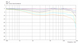
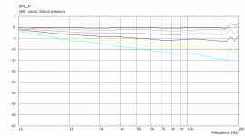
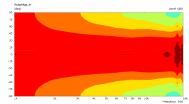
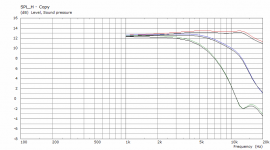
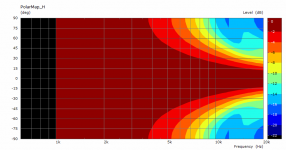
I was curious, so I ran the same script with a modified throat (to remove the extra bit of tweeter chassis) and modified the Source.Velocity and Mesh resolutions as suggested. Looks like the simulation is nice and smooth up to about 16kHz.
What tweeter is this? Design looks promising!
What tweeter is this? Design looks promising!
Code:
Source.Contours = {

zoff -2
point p1 5.2 0 2
point p2 0 13.83 1
point p3 1.75 15.58 1
point p4 0 17.33 1
point p5 1 17.33 1
cpoint c1 -15.8 0
cpoint c2 0 15.58
cpoint c3 0.435 21
arc p1 c1 p2 1.0
arc p2 c2 p3 0.75
arc p3 c2 p4 0.25
line p4 p5 0
line p5 WG0 0


}
Attachments
Last edited:
I
What tweeter is this?
This is the Seas H1212-06.
You would need to remove the grille to get the throat close to the surround, but that's an easy operation.
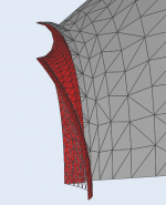
Thanks to Mabat's review of my parameters I have done another round of tweaking the model in the throat area.
Will do another run with the mesh settings suggested above and check before I'm warming up the 3D-printer.
I'm quite curious as to what phenomenon allows the off-axis response to be so good up to 20 kHz. Or is it that the model does not account for beaming (off-axis cancellation) from the diaphragm itself?
The same source can beam less when in waveguide, we have seen this before for a simple flat wavefront. The boundary conditions are simply different.
You can simulate the source alone, without a waveguide, by setting Length = 0 and Mesh.LengthSegments = 1 (this effectively removes the waveguide from the model). You'll see that the analysis is correct - it will beam.
You can simulate the source alone, without a waveguide, by setting Length = 0 and Mesh.LengthSegments = 1 (this effectively removes the waveguide from the model). You'll see that the analysis is correct - it will beam.
Last edited:
So I've been thinking a bit about the weighting of the driving elements in this simulation. Namely, how they relate to Sd, the "effective piston area" of the driver.
Using bidland's recent project as an example, if you multiply the area of each of the driving elements by it's weight constant (from the demo ath scripts) the result is larger than the listed Sd, implying that the simulation doesn't quite match the tweeter.
I did a bit of algebra and came up with the attached equations for determining the weight of both driving elements in the surround based on the geometry and the Sd from the data sheet. Let me know if it makes sense.
For the example in bidland's config file, the weights of the drive elements as calculated here are 0.67 and 0.22 for the inner and outer portion of the surround, respectively.
Attachments
That's an interesting observation. Frankly, I don't know. I'm not sure if you don't put too much emphasis on this parameter - I can imagine they set it simply by some rule of thumb and I'm actually surprised that the weights you calculated are quite close to the simple linear reduction assumption (0.75 + 0.25).
The good thing is that it is possible to experiment with this without the need to recalculate the whole model each time. These values can be changed in the observation script (observation.txt) manually and only the spectra calculated again:
It might make sense to try to adjust these weight to better match the directivity as measured in the datasheet for the sole driver first. You could even divide the surround into more than two parts but that would be probably an overkill.
The good thing is that it is possible to experiment with this without the need to recalculate the whole model each time. These values can be changed in the observation script (observation.txt) manually and only the spectra calculated again:
Code:
Driving_Values
  DrvType=Acceleration; Value=1.0
  401  DrvGroup=1001  Weight=0.25 Delay=0.0
  402  DrvGroup=1002  Weight=0.75 Delay=0.0
  403  DrvGroup=1003  Weight=1.00 Delay=0.0
It might make sense to try to adjust these weight to better match the directivity as measured in the datasheet for the sole driver first. You could even divide the surround into more than two parts but that would be probably an overkill.
Last edited:
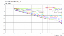
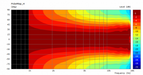
I took the bidland's tweeter model and simulated it alone in an infinite baffle. Then I also changed the weights of the surround contribution as jcarothers suggested - these are the black curves (0, 30, 60 deg):

Attachments
- Home
- Loudspeakers
- Multi-Way
- Acoustic Horn Design – The Easy Way (Ath4)