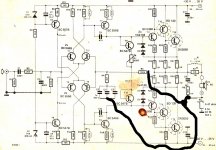
Hello you Solid State Guru’s out there. Your expertise would be highly valued, since I need your help and input in order to attempt to do a bit of experimenting with an existing ancient power amp. The amp that will be victimized was published in the Elektor’ Summers Circuits in the 80ties. The circuit, featuring the famous Quad 303 Triple output stage, has been discussed in the thread “Amplifier based on 2N3055”. I built these entirely from spare parts around 1987. Surprisingly, this is one of the few Elektor power amps I built in those years that functioned flawlessly without oscillations or other annoying side effects right from the start. The amps have been gathering dust now for some 30 years. Member Madaudio shared a somewhat stained copy of the circuit, which I reuse here. See below.
The first question I have before possible conversion into a current amp is: could the feedback capacitor, C3/4/5, which is now approx. 2.5 uF, be increased to 100 uF without limiting the functioning of the circuit? Reason is I would like to have as little phase-lead as possible in the DC-100 Hz area for the first step of my experimenting.
Main thing is: I would like to convert this Amp into a Current Drive Amp for some experimenting with 4 Ohm woofers. Basically some experimenting with low Qts woofers, but with high Qts in-box characteristics because of current drive. Bandwith needed will not exceed 1500 Hz. For that reason I would like to leave out the Zobel. To clarify my purpose: This has nothing to do with subjective issues as how Current Drive is supposed to sound, but only about woofer-amplifier interaction and investigating the woofer transfer function around in-box woofer resonant frequency. With this background in mind, I do not intend to modify other than necessary for transformation into a very basic Current Drive amp.
Could this circuit turned into something like the Joe Rasmussen Transconductance Amp as attached?
Or this: Member Adason hand drawn schematic.
General question: What should be done to turn this circuit into a working Current Drive Amp for use with a woofer-only?
Thanx for any input and help.
Eelco
Attachments

Hi!
if you want to make transconductance amp of it you have to check the stability.
My advice is to run the circuit in LTSpice, oscilation is very possible.
if you want to make transconductance amp of it you have to check the stability.
My advice is to run the circuit in LTSpice, oscilation is very possible.
Hi!
For 1.5khz bandwidth you don't really have to worry about stability, because the bandwidth of the amplifier is significantly higher than the bandwidth you desire. For that reason you can make the gain for high frequencies <1 and thus the amplifier will remain stable.
Chapter 4 of the following paper describes (albeit short) the design of current amplifier for MFB purposes: https://www.rmsacoustics.nl/papers/whitepaperMFBdesign.pdf
There's many more methods, but the paper just describes the implementation used in that subwoofer.
I also have a book about current-driving loudspeakers: Current-Driving of Loudspeakers: Eliminating Major Distortion and Interference Effects by the Physically Correct Operation Method: Merilainen, Esa: 9781450544009: Amazon.com: Books
That one goes much more in depth and proposes various methods of creating current amplifiers.
If you live near eindhoven you can borrow it if you'd like! Hit me a PM if you're interested.
I am aware of the RMS paper, but for me that is way too general and sketchy. What I am looking for is a guidance in a step by step approach.
Unfortunately I am not in the Eindhoven area, but in Amsterdam, But I may make use of the offer later. The website of Merilainen I know.
What would be a practical first step?
What would be a practical first step?
I think (others will correct me if I'm wrong) in theory you could move the feedback ground (C3-C5) to woofer -, and then use a resistor to ground the woofer -
Resistor value would adjust the output impedance of the amp. Output impedance should be roughly 22xresistor value, so 0,1ohm would give abt 2,2ohm output impedance.
BTW, using it for bass, I think the input cap and also feedback caps could have higher values.
Resistor value would adjust the output impedance of the amp. Output impedance should be roughly 22xresistor value, so 0,1ohm would give abt 2,2ohm output impedance.
BTW, using it for bass, I think the input cap and also feedback caps could have higher values.
Last edited:
It looks as if I should lift the loudspeaker minus from ground, place a large resistance of say 470 Ohms, as per Rasmussen and Adason (22 resistor value), parallel over the loudspeaker and connect the speaker to ground via a 0.33 Ohms resistor, How is voltage amplification determined in the Rasmussen diagram? And which factors determine stability in their set up?
You need to transform your amp into Holloway. Add in series with the output,0.5 ohm. Replace R2 2.2k with 4.7k and bring the R3 100k to after the 0.5 ohm instead of ground. The amp will equate the input voltage to that of the across 0.5 ohm , delivering 2A/V output current.
Hayk
Hayk
It is also called bi-phase. My-ref with lm3886 is an example. The 4.7k for R2 and R4 can be replaced by 47k.
There is no step by step guide for this rather scary diy task, I`m afraid. I am full of admiration for your bravery.
Hi,
Below is my "go to" network for mixed feedback applied to a standard voltage amplifier core. It is one of the many ways to create a dominant current drive amp from any voltage feedback power-amp (sans current-feedback topology types).
At DC and very low freq, Rf, Rg and Cdc set gains. Several combinations are possible here, things like Rf alone for unity gain at DC (for low offset) converging into current drive, or alternatively, have some voltage feedback around speaker resonance by setting Rg and Rf to the desired approximate gain at >DC (DC is still unity with Cdc not shorted). Pure current drive of standard woofers IME often needs a bit of electrical damping at the system resonance otherwise the speaker will have a nasty will of its own, notably when sightly overdriven. Every error signal the cone receives from the motor will directly inject energy into the only mechanically damped system resonance and go booom!
At higher frequencies, input from Ci starts to dominate feedback and that is taken off the current sense resistor. Resulting in an "inductive" slope of output impedance.
At very high frequencies we need to establish a stable gain (and phase) of the feedback which the amp had in the original voltage amplification setup which is 20x in this case, with no integrator function. This gain is created by the capacitive divider Chf1/2 and decoupled from the other terms by the isolation resistor Ri which sets the transition frequency which should be ideally one decade lower in frequency than the original closed-loop bandwith of the amp core. You may get away with less frequency distance by adding integration via series resistance for Chf2 and still have good resulting phase margin. Chf also represents a blank capacitive loading so we have to keep its size reasonable (100pF to 220pF was found OK for many amplifiers). This network causes output impedance to revert back to zero with increasing frequency, hence it forms a "capacitive" region of high output impedance.
Of course one can as well locate the HF feedback for stability directly at the main divider (speaker vs. sense resistor) but this makes component choice and layout more critical than the proposed scheme which automatically leads to a tight and proper high-frequency layout.
Any series L//R, when required to decouple from long capacitive speaker cables, would be directly in the speaker input wire at the amp end.
I would suggest simulating of the feedback, transfer functions and output impedance with an approximate two-pole behavioral opamp.
Attachments
Last edited:
Hello you Solid State Guru’s out there.
Your expertise would be highly valued, since I need your help and input in order to attempt to do a bit of experimenting with an existing ancient power amp. The amp that will be victimized was published in the Elektor’ Summers Circuits in the 80ties. The circuit, featuring the famous Quad 303 Triple output stage, has been discussed in the thread “Amplifier based on 2N3055”. I built these entirely from spare parts around 1987. Surprisingly, this is one of the few Elektor power amps I built in those years that functioned flawlessly without oscillations or other annoying side effects right from the start. The amps have been gathering dust now for some 30 years. Member Madaudio shared a somewhat stained copy of the circuit, which I reuse here. See below.
The first question I have before possible conversion into a current amp is: could the feedback capacitor, C3/4/5, which is now approx. 2.5 uF, be increased to 100 uF without limiting the functioning of the circuit? Reason is I would like to have as little phase-lead as possible in the DC-100 Hz area for the first step of my experimenting.
Main thing is: I would like to convert this Amp into a Current Drive Amp for some experimenting with 4 Ohm woofers. Basically some experimenting with low Qts woofers, but with high Qts in-box characteristics because of current drive. Bandwith needed will not exceed 1500 Hz. For that reason I would like to leave out the Zobel. To clarify my purpose: This has nothing to do with subjective issues as how Current Drive is supposed to sound, but only about woofer-amplifier interaction and investigating the woofer transfer function around in-box woofer resonant frequency. With this background in mind, I do not intend to modify other than necessary for transformation into a very basic Current Drive amp.
Could this circuit turned into something like the Joe Rasmussen Transconductance Amp as attached?
Or this: Member Adason hand drawn schematic.
General question: What should be done to turn this circuit into a working Current Drive Amp for use with a woofer-only?
Thanx for any input and help.
Eelco
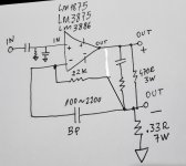
correction, I am not the author of that hand drawn picture, I just made a comment on someone else's drawing
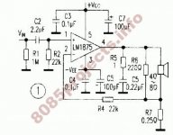
I use this schematics for lm1875
Attachments
The extra 0.47 ohm resistor needs to have a power handling in the 5 to 10 W range and very little parasitic inductance, so I wouldn't use a wirewound type. You may have to use series and parallel connections of lower power resistors, or maybe one of these: . Audyn 0.47 Ohm 10 Watt MOX Besides, you may need to add an offset trimming circuit, like a potmeter between the positive and negative supplies with a 10 Mohm resistor from its wiper to R3.
Attachments
Last edited:
Zobel should go to the ground. Speaker should be parallel with 470 ohm resistor to prevent wild voltage swings if speaker is unplugged.
Expect dc troubles.
Expect dc troubles.
No, with the Zobel to ground, the inductance of the loudspeaker causes an extra pole in the loop that probably makes it oscillate. You are right about the unplugged loudspeaker, but why do you care? With that 470 ohm shunt resistor, you much reduce the output impedance and make the current drive worse.
Last edited:
- Home
- Amplifiers
- Solid State
- Possible conversion into Current Amp?