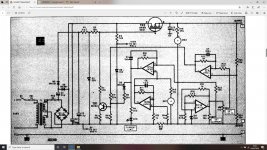
Well the symbol is definitely that of an n-channel enhancement MOSFET. It's being used as a source-follower so its probably fairly forgiving of substitute devices. The symbol shows no body diode, so its probably an early lateral FET.
The circuit looks like a lab PSU with voltage and current pot. 30Vac transformer so perhaps upto 40V output (the gate circuit is bootstrapped above this by a doubler circuit)
Try a modern lateral FET, also add a gate-source zener for protection I think.
Check if the mounting assumes case is the source or the drain. If source then most laterals will work without thermal pad.
Last edited:
IRF_P_ isn't a series, its International Rectifier's designation for TO247 packaged FETs
B = TO220
P = TO247
R = Dpak
S = D2pak
U = Ipak
etc
Many IR devices are available in several packages.
Modern switching MOSFETs are vertical, not lateral, and have the drain as the substrate, not the source.
What package type is needed? Profusion sell Exicon laterals in several packages.
B = TO220
P = TO247
R = Dpak
S = D2pak
U = Ipak
etc
Many IR devices are available in several packages.
Modern switching MOSFETs are vertical, not lateral, and have the drain as the substrate, not the source.
What package type is needed? Profusion sell Exicon laterals in several packages.
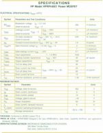
here's more on the original mosfet ...
from 1981 ....
😱
https://www.hpl.hp.com/hpjournal/pdfs/IssuePDFs/1981-08.pdf, starting on page 18.
mlloyd1
from 1981 ....
😱
https://www.hpl.hp.com/hpjournal/pdfs/IssuePDFs/1981-08.pdf, starting on page 18.
mlloyd1
A plastic-TO 247 die mosfet at 100V+ and high current will do the job ,Farnell (UK) sell them.
I am not a fan of the smaller die high current mosfets available at much cheaper prices , I replaced the TO3 mosfets in a JLH amp with the ( now out of stock ) BUZ 900P/905P plastic versions in TO-247 ---still working after many decades in class A .
I am not a fan of the smaller die high current mosfets available at much cheaper prices , I replaced the TO3 mosfets in a JLH amp with the ( now out of stock ) BUZ 900P/905P plastic versions in TO-247 ---still working after many decades in class A .
Whatever you do, don't use a modern switching MOSFET with extremely low on resistance and serious Spirito instability, as it will blow itself up. Check the safe operating area curve of any potential replacement to see if it is power limited; the allowable current should be inversely proportional to the voltage and not roll off at some faster rate.
Well the symbol is definitely that of an n-channel enhancement MOSFET. It's being used as a source-follower so its probably fairly forgiving of substitute devices. The symbol shows no body diode, so its probably an early lateral FET.
Lateral MOSFETs also have body diodes, and the symbol shows it: the connection with the arrow is the bulk.
It looks as though the guy who originally built this kit used an IRF620.
That seems to be a bit small for my liking, especially if you run the PSU at its limits, ie low output voltage at high current.
I've got some IRFP250s lurking around, I'll try one of those.
That seems to be a bit small for my liking, especially if you run the PSU at its limits, ie low output voltage at high current.
I've got some IRFP250s lurking around, I'll try one of those.
Unfortunately the originally specified meters are no longer available.
The output voltmeter (ME2) poses no problem.
I can fit any ammeter into the output circuit but does the ME1 position need to be filled with an appropriate resistor ?
I'm just using two panel DMMs, what value resistor at ME1 would read true Iout ?
The DMMs are voltmeters.
It would be nice to use the circuit as intended. My initial intention is to replace ME1 with a 68R and then measure the output current using a DMM across 1R0 at the output.
The original circuits used 2 x 65R 1mA meters.
Last edited:
My DMM reads voltage and is high resistance.
I need to adapt the circuit so that the voltage across the resistor replacing ME1 is proportional to the output current.
I can then read that voltage and convert it into a current reading.
I need to adapt the circuit so that the voltage across the resistor replacing ME1 is proportional to the output current.
I can then read that voltage and convert it into a current reading.
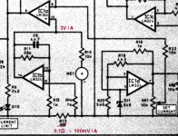
From the article, the meter should be 65 Ohms and should read 2.5A at 1mA full scale.
So if I replace ME1 with a 65R resistor, I would expect 1mA x 65R = 65mV at 2.5A.
That is not very useful for a true reading DMM.
So if I replace ME1 with a 65R resistor, I would expect 1mA x 65R = 65mV at 2.5A.
That is not very useful for a true reading DMM.
I'm figuring that I could use a 10K multi-turn pot in place of R15 and ME1 and put the DMM between the wiper and 0V.
With 1mA you get 10V at the top of R15(10k). That is 10/30V (gain IC1b is 30x) over R13 at 2,5A making it 10/(30x2,5)=0,1333333Ω 😕From the article, the meter should be 65 Ohms and should read 2.5A at 1mA full scale.
That's the second error around R13 🙁
Mona
- Home
- Amplifiers
- Power Supplies
- What MOS-FET ?