I'm rebuilding a Classe CA-401 after one channel blew out. I'm documenting the entire experience to keep track of everything I've done and to help out others. Enjoy!
Every power transistor in the channel was blown. Here's a picture of the vaporization leftovers of the 10N20 and 10P20 gate resistors. Also, check out the 383R VBE multiplier resistor residue in the top right corner:

Every power transistor in the channel was blown. Here's a picture of the vaporization leftovers of the 10N20 and 10P20 gate resistors. Also, check out the 383R VBE multiplier resistor residue in the top right corner:
Last edited:
The first thing I did was clean it up and assess the damage. I ordered replacement parts from Mouser and studied the service manual. I made the mistake of reverse polarizing the preamp board, but it might not have caused that much damage because of the 1K27 series resistors. I ordered a second batch of parts and replaced all of the electrolytics on the preamp board. Amazingly, the preamp board appeared to be working when I loaded the output transistors with a 1K resistor shunted between them. I could only power up the preamp board to +- 30V DC.
I also replaced the protection circuitry (6V8 Zener diodes and 1N4003 diodes) on the output board along with all of the emitter resistors, 6 MJ21193 & 10P20, 6 MJ21194 & 10N20. Obviously, I had to replace the 200R gate resistors because they vaporized.
Next up for replacement was the VBE MJE2222A, the 383R, and the 5K multi-turn trimmer. I probably could have used a 2K multi-turn trimmer, but the other side has a 5K trimmer.
Next up for replacement was the VBE MJE2222A, the 383R, and the 5K multi-turn trimmer. I probably could have used a 2K multi-turn trimmer, but the other side has a 5K trimmer.
Last edited:
I also replaced a 4R7 resistor on the processor board that looks like some sort of zobel network. The relay switch connected to it appears to be related to bridge mode.
The service manual says that there is some sort of way to power up the amp out of protection mode with a variac. Unfortunately, I couldn't find the taps to connect to and the service manual is really difficult to comprehend.
Here are the instructions from the service manual:
I couldn't figure out a way to access the soft start bypass wire tabs so I powered it up outright.
The service manual says that there is some sort of way to power up the amp out of protection mode with a variac. Unfortunately, I couldn't find the taps to connect to and the service manual is really difficult to comprehend.
Here are the instructions from the service manual:
Start Up Procedure
When receiving a unit, an assiduous visual inspection must be performed. Do not connect the unit without
analysing the symptoms reported by the customer and the results of the inspection.
Using the troubleshooting guide, find the problem and proceed to the repair. Once this step is done, follow
these steps, known as the start-up procedure, to ensure that everything in the unit is in working condition.
1. Proceed with a post repair visual inspection. Take the time to check if every wire is reconnected
properly, every screw is bolted on, no soldering and/or metal residues lying in the unit, every fuse has
been replaced, etc.
2. Connect the unit to a variable transformer, setted to 0Vac.
3. Turn the bias trimpot (RV1) counter clockwise until a click is heard.
4. Connect the bypass wire to the variable transformer. This bypass is a power cord, modified on the
female side in order to bypass the soft start sequence. It is connected to the line tab on voltage
selector PCB.
5. Slowly raise the voltage to 10Vac, and check positive and negative rails and pre-driver supply. Check
fuses.
6. If one or more supply are not within specifications, return to the troubleshooting guide.
7. Slowly raise voltage until you hear relays click, this point is around 55Vac. Recheck every supply.
8. If one or more supply are not within specifications, return to the troubleshooting guide.
9. Raise voltage to 120Vac. Recheck every supply
I couldn't figure out a way to access the soft start bypass wire tabs so I powered it up outright.
Powering it up was a problem and the 4R7 resistor heated up. I had a multimeter attached to each output and I could see the voltage climb up to 20 volts on the bad channel and then it would cut off after a relay switched. The front panel led when from flashing red to solid, so I assumed it was not OK, but stable. Also, one of the outputs had a 100mV offset. The good channel had a 10 microvolt offset.
Here's the circuit with the 4R7 resistor, R1 and R2, connected directly to the output and the MOSFET PSU. I'm not sure if a missed a bad fuse in the MOSFET supply before I powered it up or if I blew the fuse myself. Regardless, I replaced the fuse and I stopped getting a huge voltage swing before the final relay click.
There's a possibility the relay might be fused shut.

There's a possibility the relay might be fused shut.
Even though there might be a bad output sense op-amp in the circuit, I figured it would be best to replace it last so I could continue troubleshooting the circuit.
Next up was bias adjustment. Bias adjustment did absolutely nothing. I scratched my head on this one for a while. Eventually, after poking and probing the circuit for an hour or so, I figured out that the lead from the 383R VBE resistor was poking into the heat sink and shorting the VBE transistor to ground!!
Next up was bias adjustment. Bias adjustment did absolutely nothing. I scratched my head on this one for a while. Eventually, after poking and probing the circuit for an hour or so, I figured out that the lead from the 383R VBE resistor was poking into the heat sink and shorting the VBE transistor to ground!!
Clipping the lead from the VBE circuit didn't help much. I put the amp back together and the bias still doesn't do anything. I can't remember if I checked to see if the MOSFET supply turned on or not. I looked over the schematic some more and the mosfet protection circuit looks pretty robust. I still haven't connected it to a load. I'm guessing that maybe I blew a MOSFET or there is something wrong with the preamp board.
In retrospect, this was a terrible idea, but I took out the preamp from the good channel and it appeared to work just fine in the channel I was troubleshooting. Putting the good preamp back in the good channel caused a fault in the channel!!! and the red LED on the computer board right next to the zobel network started flashing when the second relay kicked in. I was so mad.
Thinking things over:
1.) I could have damaged the good preamp by removing it or installing it while the caps were still energized, This amp takes minutes to discharge the caps.
2.) The MOSFETS on the initial bad channel could have been damaged and damged the good preamp.
3.) Maybe I should have replaced the bad sense op-amp associated with the computer.
Last edited:


I'm not sure if I'm going to remove both channels and power them up with separate power supplies for both the MOSFET circuit and the output circuit next. Monitoring current could be helpful.
It's a good practice to make a detail service record, thanks for sharing.
I checked your amp schematic and it seems quite good amp circuit design with such a huge power transformer and the sounding can be expected very good.
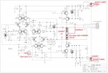
Here is the schematic :
Classe Audio CA-401 - Manual - Power Amplifier - HiFi Engine
Hope you rebuilt successful
I checked your amp schematic and it seems quite good amp circuit design with such a huge power transformer and the sounding can be expected very good.
Here is the schematic :
Classe Audio CA-401 - Manual - Power Amplifier - HiFi Engine
Hope you rebuilt successful
I'm not sure if I'm going to remove both channels and power them up with separate power supplies for both the MOSFET circuit and the output circuit next. Monitoring current could be helpful.
For easy and safe to repair the preamp boards, you can testing the preamp boards outside the amp by using diodes to simulate the VBE multiplier circuit and connect power supply with supply rail diode protection.
Attachments
Last edited:
Thanks for the comments Patrick101!
I've got some more time to poke at this amp today. The capacitor discharge time constant for the power transistors takes over 15 minutes! I've been twiddling my thumbs for over 10 minutes and have only gotten to 50 volts from 95 volts. There is 47000F at 95V discharging through a 20K resistor for each rail. Hot swapping might have screwed up the other channel.
It appears that I blew the DZ103 and DZ104 on one board. DZ103 and DZ104 are TL431 programmable voltage references. I think that the MPSA18 and MPS4250 blew up on the other board. I'll keep everyone posted. I've got to stop now.
Last edited:
There is 47000F at 95V discharging through a 20K resistor for each rail. Hot swapping might have screwed up the other channel.
Waiting the 20K to discharge the big cap reservoir will spent a long time, so that when repairing the amp, we can add 2 extra 5K 10W resistor parallel to the 20K to reduce the discharge waiting time and it will not affect the repairing job.
It appears that I blew the DZ103 and DZ104 on one board. DZ103 and DZ104 are TL431 programmable voltage references. I think that the MPSA18 and MPS4250 blew up on the other board. I'll keep everyone posted. I've got to stop now.
Your amp is so heavy and big size, but lucky that the circuit is not so complicate and I think you can fix it easily.
Please show us more pics, thanks!
Here is a picture of the discharge resistors on the capacitor board. I don't have room to put bigger resistors in there!

Here is a picture of the mounting posts and the power transformer input board. There are even more caps on this board than in the schematic. You can see the 100 ohm ground lift resistors and caps in the bottom of the photo.

I'll post some closeups of the amp boards soon.
Here is a picture of the mounting posts and the power transformer input board. There are even more caps on this board than in the schematic. You can see the 100 ohm ground lift resistors and caps in the bottom of the photo.
I'll post some closeups of the amp boards soon.
Maybe temporarily install the resistors by extended cables for repairing discharge purpose.
Last edited:
Hi. is there any update about the amp?
Does somneone know a source for the proccesor/ cpu as mine is defective and is in a repair shop for more than two year s😱
Does somneone know a source for the proccesor/ cpu as mine is defective and is in a repair shop for more than two year s😱
Hello, im repairing this model of amplifier, the driver boards from both channels looks identical, are they interchangeable with each other?
mine amplifier has dead one channel, but without visible damage, just shorted drivers and outputs and few emmiter resistors.
I measured transistors on driver board and they look working, but before i put whole channel tigether i would like to check the driver board In second working channel for test purpose. After all i will change all of the 12 pairs of outputs and 2 pairs of drivers to ge both channels equal
- Home
- Amplifiers
- Solid State
- Classe CA-401 Rebuild