Hello!
New member here. Was told to post here from a member on AudioKarma.
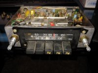
I have 2 vintage toyota 2ch AM/FM radios from the late 70's / early 80's that have issues. Both radios were "tested" in my room with a single speaker, no antenna and a 13.8v power supply. I wish I had a schematic, but I do not 🙁
1. Radio one turns on, will pick up a few stations when I've got my hand near it (acting as the antenna), but one channel has a continuous "popopopopop", or if it isn't popping, the audio is super quiet compared to the other channel. It uses two MB3713 5.7 watt power amplifiers that I assume are the output amps. I'm assuming the one for the channel that is popping is bad?
2. Radio one also has a balance control, though it doesn't appear to do much aside from make the audio quality worse on the channel that works. Any ideas?
3. Radio two turns on, and that's it. No noise to the speaker on either channel, no stereo indicator. However, the back of the radio where the power amps are sinking to gets super hot within 10-15 seconds. I'm assuming both power amps are shorted?
I've got an oscilloscope and one of those bluetooth-to-fm devices, I was thinking about using that, playing a solid 1khz tone, and checking the input on all the amp packs with the oscope to see if the tuner portion is working properly.
New member here. Was told to post here from a member on AudioKarma.
I have 2 vintage toyota 2ch AM/FM radios from the late 70's / early 80's that have issues. Both radios were "tested" in my room with a single speaker, no antenna and a 13.8v power supply. I wish I had a schematic, but I do not 🙁
1. Radio one turns on, will pick up a few stations when I've got my hand near it (acting as the antenna), but one channel has a continuous "popopopopop", or if it isn't popping, the audio is super quiet compared to the other channel. It uses two MB3713 5.7 watt power amplifiers that I assume are the output amps. I'm assuming the one for the channel that is popping is bad?
2. Radio one also has a balance control, though it doesn't appear to do much aside from make the audio quality worse on the channel that works. Any ideas?
3. Radio two turns on, and that's it. No noise to the speaker on either channel, no stereo indicator. However, the back of the radio where the power amps are sinking to gets super hot within 10-15 seconds. I'm assuming both power amps are shorted?
I've got an oscilloscope and one of those bluetooth-to-fm devices, I was thinking about using that, playing a solid 1khz tone, and checking the input on all the amp packs with the oscope to see if the tuner portion is working properly.
Attachments
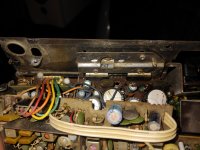
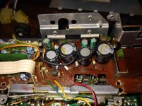
The black goo by the electrolytic cap on the bottom PCB could be electrolyte that's leaded out of the cap. In that case the cap is done, and the PCB likely is too.
I like your idea of using the BT-to-FM transmitter as an RF source for testing. That should work pretty well. You can probably get away with a short length of wire (3'/90 cm should be about right) jammed into the antenna jack as an antenna.
Don't mess with any of the inductors, transformers, or adjustable capacitors. Without the proper tools and alignment procedure, you're not likely to get the demodulator back into alignment once it's out.
Tom
The black goo by the electrolytic cap on the bottom PCB could be electrolyte that's leaded out of the cap. In that case the cap is done, and the PCB likely is too.
I like your idea of using the BT-to-FM transmitter as an RF source for testing. That should work pretty well. You can probably get away with a short length of wire (3'/90 cm should be about right) jammed into the antenna jack as an antenna.
Don't mess with any of the inductors, transformers, or adjustable capacitors. Without the proper tools and alignment procedure, you're not likely to get the demodulator back into alignment once it's out.
Tom
I think the black goo is some sort of celastic as its on both of the large caps. The reason it looks wet on the right side is cause I mistakenly used the deoxit that both cleans and lubricates electrical connectors on the power button, vs using the deoxit that just cleans. I meant to clean the control, then use the cleaning lube, but got the two products backwards.
If I can, I will take some pictures of the process. I am hoping just the amps are damaged. Testing the radio where both channels are dead will be interesting since they are both acting like they are shorted and are getting hot. I may cut the power the power leg so they dont burst into flames while I am testing the input signal.
As for the adjustables, sounds good. We went over that type of stuff in college, and without a schematic or the factory procedure, if I messed with the controls, the radio is as good as junk.
Generally the output transistors or chip amps won’t go bad on their own.
I would look at the old, dried out electrolytic capacitors, and start there, after an overall cleaning.
I would look at the old, dried out electrolytic capacitors, and start there, after an overall cleaning.
Generally the output transistors or chip amps won’t go bad on their own.
I would look at the old, dried out electrolytic capacitors, and start there, after an overall cleaning.
How should I go about checking them?
How should I go about checking them?
By using the proper tools of the repair trade, of course.
Certainly you have such tools?
By using the proper tools of the repair trade, of course.
Certainly you have such tools?
Descriptive answer...
In terms of tools, I have a dmm, oscilloscope, and a soldering iron. I just need to know what to look for. My dmm can measure capacitance, but not eat. Do the caps need to come out to check them? What about resistors? What about the transistors what have vague writing on them..?
Have you tried to find a service manual for the head unit?
Yes, with no luck. I don't think Toyota ever designed these radios to be worked on, let alone by the public.
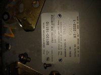
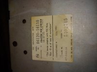
Post all numbers on the chassis and face so others can look.
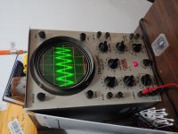
Here you go. Attached also is a picture of the output section of the board, as well as a picture of the good wave form on the radio that has one working channel.. Stupid me didn't get a picture of the bad channel. It looked like straight noise--no distinct waveform, and the image filled the whole screen. I wasnt able to adjust the settings to get a better picture. 90% of the controls don't work currently on this eico. I have a tektronix my friend gave me, but I need to order a set of probes...
I noticed that the amp with the popping is small getting very hot like the other radio. My guess is the failure mode between the radios is the same.
Attachments
Question--
On stereomanuals.com, they have the service manual for the FujitsuTen AT-2332-1 radio (toyota 86120-14170). Visually, the radios look identical, and were made during the same time period. They were installed on the mid 77-80 celicas. Do you think it'd be worth buying? The celica radio also appears to be a 2ch am/fm radio...
Toyota High Quality Service Manuals User Owner Instruction Manuals Schematics Brochures Literature Printed PDF (some FREE)
$17 for some is beyond their budget. For others, it's absolutely nothing. You'll have to decide if it's worth it to eliminate much of the guesswork.
$17 for some is beyond their budget. For others, it's absolutely nothing. You'll have to decide if it's worth it to eliminate much of the guesswork.
I gotcha. I hope the radios are close enough internally to the one the manual covers to make it worth the buy. My concern is that the manual is for a different radio that the ones I have. Just cause the radios look the same doesn't mean the insides are the same...
I'll report back when I get the manuals in the mail!
Minor update--
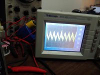
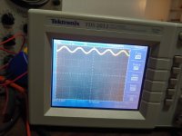
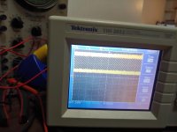
Got some leads for the tektronix. Confirmed that the bad amp is getting the same input as the good amp in the first radio. My guess is a bad amp. However, without the schematic, I can't confirm this. Should get the service manual sometime this week. Any thoughts on the scope pictures? The output of the good amp looks like it has a DC offset?
Got some leads for the tektronix. Confirmed that the bad amp is getting the same input as the good amp in the first radio. My guess is a bad amp. However, without the schematic, I can't confirm this. Should get the service manual sometime this week. Any thoughts on the scope pictures? The output of the good amp looks like it has a DC offset?
Attachments
Hello.Minor update--
Got some leads for the tektronix. Confirmed that the bad amp is getting the same input as the good amp in the first radio. My guess is a bad amp. However, without the schematic, I can't confirm this. Should get the service manual sometime this week. Any thoughts on the scope pictures? The output of the good amp looks like it has a DC offset?
MB3713 Amp Kit page includes schematic which should be close to what is in the radios, also MB3713 Datasheet .
Pin 1 should measure around half the supply voltage so 6V or so.
Idle current should not be high, it would be best to use a 'bulb tester' in series with your DC supply whilst diagnosing.
The brown/black stuff was yellow contact glue but has decomposed to the dark colour it is now, it is also corrosive and conductive so remove all bridges.
The smaller size electro caps are likely dry by now and it would be advisable to replace them, the two larger sizes are also suspect by now, replacement MB3713 are easily available.
Is there a special reason to get these radios working again ?.
Max.
Great project, the best of luck with it.
A random tip, if the plastic parts at the front come off en bloc, putting them in an ultrasonic cleaner with a bit of dish soap is worth trying before any sort of solvent to clean them up.
A random tip, if the plastic parts at the front come off en bloc, putting them in an ultrasonic cleaner with a bit of dish soap is worth trying before any sort of solvent to clean them up.
How should I go about checking them?
I would plan on replacing them at that age/environment myself.
Foxx1996, can you read the part# on the power IC's?
I have an 80's Toyota head unit that was working fine when I took it apart, there are two AN7173K's in that one.
I have an 80's Toyota head unit that was working fine when I took it apart, there are two AN7173K's in that one.
- Home
- General Interest
- Car Audio
- Vintage toyota am/fm radio woes