First post is actually post #4 under
https://www.diyaudio.com/forums/solid-state/340058-accuphase-300s.html#post6095754
maybe the moderation can filed this post and the post #6 in this topic.
https://www.diyaudio.com/forums/solid-state/340058-accuphase-300s.html#post6095754
maybe the moderation can filed this post and the post #6 in this topic.
Attachments
-
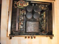 P-300X top view.jpg1,004.6 KB · Views: 1,392
 -
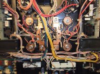
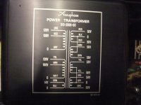 P-300X Mains Transformer.jpg994.9 KB · Views: 832
 -
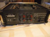 P-300X back pannel.jpg993.3 KB · Views: 854
 -
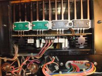 P-300x output stage-I.jpg1 MB · Views: 830
 -
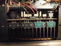 P-300x output stage-II.jpg1,010.3 KB · Views: 1,241
 -
 P-300x output stage-III.jpg990.8 KB · Views: 461
 -
 P-300X speaker select.jpg988.2 KB · Views: 435
 -
 DSCF5591.jpg996.8 KB · Views: 392
 -
 DSCF5592.jpg985 KB · Views: 367
 -
 DSCF5593.jpg999.7 KB · Views: 451
Last edited:
images level meter control PCB
Attachments
-
 P-300X PCB Level-Meter-Contr-I.jpg983.1 KB · Views: 448
 -
 P-300X PCB Level-Meter-Contr-II.jpg561.1 KB · Views: 345
 -
 P-300X PCB Level-Meter-Contr-III.jpg1,004.3 KB · Views: 279
 -
 P-300X PCB Level-Meter-Contr-IV.jpg985.8 KB · Views: 259
 -
 P-300X PCB Level-Meter-Contr-new elcaps-I.jpg1 MB · Views: 300
 -
 P-300X PCB Level-Meter-Contr-new elcaps-II.jpg997.8 KB · Views: 304
 -
 P-300X PCB Level-Meter-Contr-new elcaps-III.jpg1,009.9 KB · Views: 286
 -
 P-300X PCB Level-Meter-Contr-V.jpg990.4 KB · Views: 291
 -
 P-300X bottom view-II.jpg1 MB · Views: 284
 -
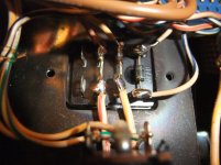 P-300X inrush current lim. Rel.jpg995.6 KB · Views: 327
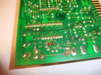
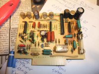
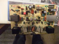
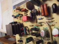
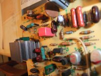
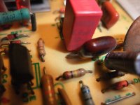
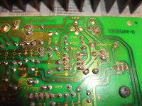
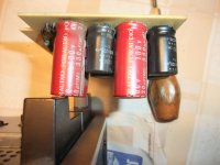
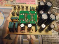
images power amp PCB and power supply PCB for the front end unit
Attachments
-
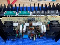
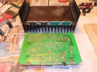 P-300x power amp right ch PCB-I.jpg1,005.5 KB · Views: 402
 -
 P-300x power amp right ch PCB-II.jpg1,002.5 KB · Views: 478
 -
 P-300x power amp right ch PCB-III.jpg988.1 KB · Views: 355
 -
 P-300x power amp right ch PCB-IV.jpg982.7 KB · Views: 345
 -
 P-300x power amp right ch PCB-V.jpg979.2 KB · Views: 310
 -
 P-300x power amp right ch PCB-VI.jpg1,004.4 KB · Views: 359
 -
 P-300x PCB PS front end.jpg854.2 KB · Views: 360
 -
 P-300x PCB PS front end-II.jpg869.9 KB · Views: 345
 -
 P-300x PCB PS front end new caps-I.jpg1,007.5 KB · Views: 399
 -
 P-300x PCB PS front end new caps-II.jpg1,009.4 KB · Views: 389
I have the same amp circuit board that has no variable resistor for voltage adjustment, we probably have a later revised board as the earlier P300X had the VR for voltage.
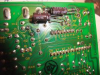
Anyone knows the d12 model number who check is the one attached on the heatsink printed "0DB"? I think it is difficult to find a new one for my bad one.
To, thanks for your info. Btw, I've tried to found this out but unluckily there's nothing found from eBay or any link. Does anyone have idea to get one or any other replacement unit could fix it? It is very annoying issue.
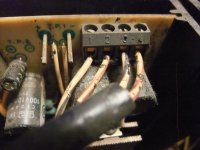
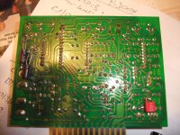
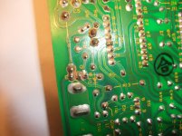
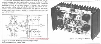
Sorry for warming up an old thread. The PCB shown in post #5 is one of four types i've encountered. Maybe there are more, guess this amp was hugely successful and hence went alterations during active production period.
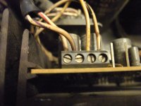
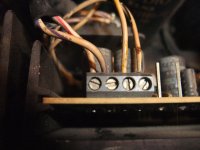
The first two iterations have the black/clear relay, the one in patrick101's post has the connector block near Q16/Q22, the other one has not. A third one has a connector block near C12/C13, the 2nd one just a hole that lets the cable pass through for handwired joints on the solder side of the PCB.
A later PCB has the second pot (offset) eleminated. An even later one carries the red NEC relay which seems to be more reliable (also used in quantity inside P-300L/P-300V). Oops, maybe these were five types already.
My guess is that the threadstarter's P-300X had a complete module exchange at some point for the 2nd last version PCB with just the one bias pot, but still the earlier black/clear relay fitted.
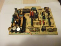
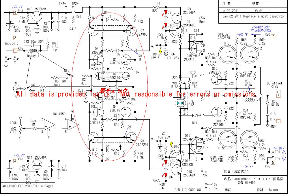
The circuit diagram in post #7 lacks R31 at Q12 collector (10R, same as R30), and shows 150R for R34, where i have always seen 56 Ohm.
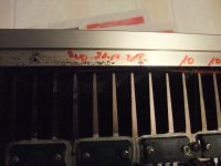
I also note that earlier P-300X don't have those 3 parallel resistors R9/10/11 on the driver psu pcb carry quite so much current (no board discoloration). Some later P-300X even have an extra large hole in the beauty-cover to allow that heat getting away. Not a great success in most i've seen, the top lid is just a few mm away
Nice amp otherwise, very full-bodied, maybe even a bit on the warm side of neutral. Great for otherwise lean-sounding setups !
All the best,
Ralph
The first two iterations have the black/clear relay, the one in patrick101's post has the connector block near Q16/Q22, the other one has not. A third one has a connector block near C12/C13, the 2nd one just a hole that lets the cable pass through for handwired joints on the solder side of the PCB.
A later PCB has the second pot (offset) eleminated. An even later one carries the red NEC relay which seems to be more reliable (also used in quantity inside P-300L/P-300V). Oops, maybe these were five types already.
My guess is that the threadstarter's P-300X had a complete module exchange at some point for the 2nd last version PCB with just the one bias pot, but still the earlier black/clear relay fitted.
The circuit diagram in post #7 lacks R31 at Q12 collector (10R, same as R30), and shows 150R for R34, where i have always seen 56 Ohm.
I also note that earlier P-300X don't have those 3 parallel resistors R9/10/11 on the driver psu pcb carry quite so much current (no board discoloration). Some later P-300X even have an extra large hole in the beauty-cover to allow that heat getting away. Not a great success in most i've seen, the top lid is just a few mm away
Nice amp otherwise, very full-bodied, maybe even a bit on the warm side of neutral. Great for otherwise lean-sounding setups !
All the best,
Ralph
check out for further information this thread:
https://www.diyaudio.com/community/...-p-500-and-others-diagrams-repair-etc.211108/
https://www.diyaudio.com/community/...-p-500-and-others-diagrams-repair-etc.211108/

Sorry to resurrect this old thread. Does anyone know the correct default bias for the P300X? I’m not sure if the circuit diagram I found is accurate, and 6.2mV seems a bit low. Thank you in advance.
I recently serviced my P-300X. Without a service manual available, the bias current is set based on the idle power it draws from AC mains.
The P-300X brochure specifications show 80W without signal, setting the bias voltage to 10mV hits that mark. The heatsinks are comfortably warm.
Changing the three speaker relays, small signal relays and re-seating the output transistors (clean off old goop and apply new) were good improvements. The BJT's temperature lowered 5ºC after the cleaning and re-seating compared to before.
Attachments


6.2mv is the correct factory setting. 10mv will make your amp run hotter. Accuphase is always spot on so what they list in the SD or SM is what you should follow. I personally dropped to 5mv so those
Unobtanium original output transistors don’t get too much heat. Makes it last longer and all other components on the amp board are not stressed out.
Unobtanium original output transistors don’t get too much heat. Makes it last longer and all other components on the amp board are not stressed out.
Interesting, do you have the Accuphase SM for the P-300X stating 5mV?
At 5mV the idle power drawn is not close to 80W.
At 5mV the idle power drawn is not close to 80W.
Initially, I found the left channel at around 13mV and the right channel at 20mV, so I adjusted both to 20mV. However, after warming up, I noticed the temperature was too high, so I lowered them to 7mV. Thanks for your advice. I have service manuals for the 300, 300L, and 300V, but I just can’t find the correct information for the 300X.I recently serviced my P-300X. Without a service manual available, the bias current is set based on the idle power it draws from AC mains.
The P-300X brochure specifications show 80W without signal, setting the bias voltage to 10mV hits that mark. The heatsinks are comfortably warm.
Changing the three speaker relays, small signal relays and re-seating the output transistors (clean off old goop and apply new) were good improvements. The BJT's temperature lowered 5ºC after the cleaning and re-seating compared to before.
- Home
- Amplifiers
- Solid State
- Accuphase P-300X (P300X, not P-300/P-300S) schematic wanted