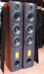
I have a pair of Triangle Celius 202 (vers 1) that has two thermistors per speaker on the crossover pc board.
I rebuilt them using better parts (caps). At that point I thought the thermistors were just their way of having a fuse in circuit to protect the drivers. I read in one place to leave them and in another to pull them and replace with wire. So of course I measured the resistance at 72F and replaced with mills 5w of those values (.62 & .75 ohms). So everything was good except one of the caps I added failed after a few years, so when I opened up I figured, hey try the straight wire change on one.
It's very different, very bold and louder sounding (that's a lot resistance taken out), but the depth seems gone - the other way they sound like very stately dipoles. Coherent, flat, good depth, clean taut bass, but maybe too tame.
I know now the thermistors were to change resistance if the crossover got heated to a certain temp to keep the behavior of the drivers/xover in sync with the change. I dont know what the original values were, and Triangle is legendary for not dealing with products that are no longer made.
I don't listen loudly so the change over feature of the thermistor isn't a big deal, not enough to deal with it. So what's my recommended move here? I don't think an SPL meter will clue me in. Given no input I'll go back to the resistors back in.
The idea of parts in a crossover changing value with heat is one I have also seen in Duelund
Are you sure they weren't just fuses?
Best,
E
Are you sure they weren't just fuses?
Best,
E
I mean, are you sure the thermistors weren't meant to act as fuses, as opposed to actually be compensating for some other part of the circuit?
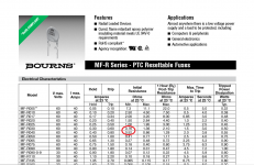
Those "thermistors" are PolySwitch fuses. You can replace them with resistors, but be careful with the volume knob.I have a pair of Triangle Celius 202 (vers 1) that has two thermistors per speaker on the crossover pc board.

Thank you.
I do remember when I took them out and looked them up, they went from one R value to another - so I wondered that's not a fuse... then the wife tossed them (they were on the floor, and they looked like crap), and I tried Triangle to no avail, so all I had left was the quiescent measurements I took.
These are notes I took at the time in case anyone is interested in these:
Xover parts list (changed them all from stock/generic parts; did not change inductors)
R1 5.6 ohm (mills 5 watt)
R2 1.0 ohm (mills 5 watt)
P1 .75 ohm (mills 5 watt) (P=termistors - tested the value from them at 72 degrees, and replaced)
P2 .62 ohm (mills 5 watt)
C1 47 uf (Elna Silmic II 100 v)
C2 " " "
C3 22 uf Aeon 250 v
C4 (see C1 values)
C5 4.7 uf Clarity Cap 250 v (bypass Jensen .01 uf 3k v (NOS))
C6 15 uf Aeon 250 v
L-pad: Mundorf 47 ohm and 1.2 ohm - a 1.35 db decrease of the tweeter (diff room then, out now)
First thing I did, is set up the L-pad. It was a subtle effect, similar to putting a couple of 2x3 scatter rugs on a concrete floor between the speakers and the seating position. I liked it, so I did the same change to the other speaker. I further decided in looking over the xover that I could make more changes for a reasonable price. I changed the resistors first - as one could expect nothing beyond audio nervousa.
The cap changes however (just to one speaker) very notable. Complex music (two cellos, bass, female vocalist for instance) seemed to become less smeared and cleaner, and my precious sense of harmonics? Back. Not to the level of a Martin-Logan CLS or Verity Parsifals, but well more than the metallic/aggressive high end that suppressed harmonics to my ear from these in stock condition. Both the L-pad and cap changes had something to do with the changes. It's easier to relax in front of the music than it has been - that's good.
I found an old ad circular on these, and it says "internal protection" - so the thermistors were not to change the xover value, but instead interrupt if the temp got too high.
Having mills resistors as opposed to the thermistors might not protect me for heavy use (not an issue for me), but at least from an audiophile 'purist' POV they should be 'cleaner'. I'm going with that, and not looking back.
Having mills resistors as opposed to the thermistors might not protect me for heavy use (not an issue for me), but at least from an audiophile 'purist' POV they should be 'cleaner'. I'm going with that, and not looking back.
I can't make sense of the crossover without seeing a properly drawn schematic:
Downloads
This sort of design has a few strengths. A midrange spared from bass duties, with a design optimised for midrange. And cloth surround is a good thing, IMO. Bit like this:
https://boxsim-db.de/rhytmic/
You could import that one into the projekte folder and have a play with it.
But really, by losing the polyfuses you are just upping level a tidge. It's not fundamentally improving the speaker. Nor is changing components, except maybe aircoils work better than ferrites in some measurable way. This sort of thing is really just moving the furniture around.
Precise advice depends on circumstances, but there are some quite advanced crossovers that address some of the irritations of loudspeakers. For instance, metal tweeters can be improved by adding a 7.5R plus 0.68uF Zobel, IMO. A flat impedance can make a speaker unfussy about amplifiers too. You can notch cone breakup around 5kHz. It is considered a good thing to align coils at right angles to avoid interactions too.
So welcome to the hobby.
Attachments
duc, I think you are right that without a PTC thermistor in series with a tweeter will bring you mildly higher SPL especially when it still hasn't recovered from overcurrent condition while maintaining higher resistance value. In practice there is a minor XO frequency change when thermistor trips but it's nothing to worry about. This is a sim of idealized drivers with only difference being a series resistor of 1R5 which should simulate a PTC at work.
Attachments
There are two different crossovers. The one that's here is the 2nd. Mine is the 1st, and mine appears to be a good deal more elemental.
I have been running w/ the replacement resistors for about 4 years now, and just changed one to a straight wire for a few weeks, and it's back to the resistor any day now because I don't like the straight wire sound at all.
I agree that air coil inductors is better than the cheaper iron core solution. However: better caps (no not silver oil) do have a profound impact on sound.
Thanks for all ideas....
Attachments
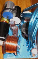
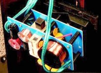
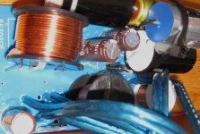
oops, the other two pics of the original xover didn't come thru. This is my handiwork, note that the xover is on one board not two like the other pic. I'll try to draw up a schematic. Here is the parts list:
R1 5.6 ohm (mills 5 watt)
R2 1.0 ohm (mills 5 watt) (that seems like a lot)
P1 .75 ohm (mills 5 watt) (P=termistors - tested the value from them at 72 degrees, and replaced)
P2 .62 ohm (mills 5 watt)
C1 47 uf (Elna Silmic II 100 v)
C2 " " "
C3 22 uf Aeon 250 v
C4 (see C1 values)
C5 4.7 uf Clarity Cap 250 v (bypass Jensen .01 uf 3kv)
C6 15 uf Aeon 250 v
L-pad: Mundorf 47 ohm and 1.2 ohm (very slight shelving down of the tweeter (due to room)), not needed in my new room, so they are gone.
I've seen schemes like this in other speakers. I had speakers that had what looked like fuses, but were really light bulbs, in the crossover. When you poured the coals on, you could see them flashing inside the cabinets. They really mucked up the sound too. I guess they do keep you from burning up your mids and tweets though.
In case anybody is still interested in the Triangle Celius 202's, or my next move:
I installed a pair of Fountek X3.0 using the connection to the xover that the old tweets were using. No way to get them in cabinet without wrecking it, so I used thick angle brackets to mount to top of speaker above the old tweeter, and angled them down a bit so they are head on my head position.
They cross over at 3.9 KHz at 12 db/octave, and have a -1.35 db L-pad in front of them.
No measurements yet. They sound maybe 1.5 db higher than the old tweets. Have kept the volume low as I try and hear any stress on the driver at the bottom of the range (no issue so far).
They are a bit less sibilant, seem to have less body - being more subtle, somehow feel to be working less hard. They capture recording space, mic set-ups better. I'd say the images are narrower probably due to less dispersion.
Both of my sons have great ears for strings and they think things have less of a highlight feeling and more of everything fits gestalt whole thing going.
I'll be back in weeks or months with some readings and final thoughts. I doubt I'll go backwards. I found a $25 discount on line on a PE purchase over $100. They are not cheap, and the diff is NOT as great as the cap replacements and thermistor replacements in the xover - but it's more than 1/2 of it.
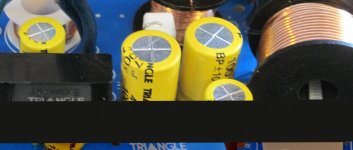
Why are you using polarised caps (Elna silmics) in place of the non polar caps (Yellow - Triangle ones) ??????
Amazed no one else has commented on this.
Probably another case of changing everything to "better" components without trying to understand the basics of circuit design that led to the original choice.
I wouldn't be surprised if the sound changes, as the polarized cap will exhibit a large leakage current with each 'wrong' half-wave of the signal, acting like a low resistance and probably adding significant distortion.
Regards,
Rundmaus
I have a pair of Triangle Celius 202 (vers 1) that has two thermistors per speaker on the crossover pc board.
I rebuilt them using better parts (caps). At that point I thought the thermistors were just their way of having a fuse in circuit to protect the drivers. I read in one place to leave them and in another to pull them and replace with wire. So of course I measured the resistance at 72F and replaced with mills 5w of those values (.62 & .75 ohms).
So everything was good except one of the caps I added failed after a few years,
so when I opened up I figured, hey try the straight wire change on one.
It's very different, very bold and louder sounding (that's a lot resistance taken out), but the depth seems gone - the other way they sound like very stately dipoles. Coherent, flat, good depth, clean taut bass, but maybe too tame.
I know now the thermistors were to change resistance if the crossover got heated to a certain temp to keep the behavior of the drivers/xover in sync with the change. I dont know what the original values were, and Triangle is legendary for not dealing with products that are no longer made.
I don't listen loudly so the change over feature of the thermistor isn't a big deal, not enough to deal with it. So what's my recommended move here? I don't think an SPL meter will clue me in. Given no input I'll go back to the resistors back in.
Let me guess, one of the polarised silmics......
Thanks for pointing it out. I do have a lot more experience with kits and plans, but I've done enough work with tweeters/xover interface (DQ-10, ProAc Tablette, DCM TW's) and my years in medical PC board stuffing, inspection, and soldering not to confuse polarized and non polarized caps. Must have transcribed it wrong.
I'll obviously fix that, and have even more to report.
I'll obviously fix that, and have even more to report.
- Home
- Loudspeakers
- Multi-Way
- thermistors in crossover