You may have seen this neat dc/dc available recently, especially given the wide variable B+ setting capability, and quite high power rating, and ability to run off 12VDC.
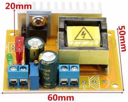
For low power valve amps (eg. up to 6V6 push-pull) they should make it very convenient to power just from a 12VDC 4-5A plug-pack.
The initial intrigue is what control IC's are used, as the 8-pin packages are defaced.
To help the guessing game, the attached doc has my first pass at a schematic drawing. No doubt I've misinterpreted a few parts, and the IC pin numbers are based on what I think are the pin 1 dimples that haven't been defaced completely.
Some strong power saving pulse skipping is going on, which appears as low frequency ripple at times, and at other times it is just pulse skipping at 70kHz ripple. The FET drain waveform is pretty clean and fast, given the simple pcb and parts. The current sense filter cap ground and IC ground seem a compromise of layout. The turn-on appears to be trying to occur close to a zero-voltage dip. No load loss is pretty good.
http://dalmura.com.au/projects/YH11068A.pdf
Ciao, Tim
I have one of the fully populated bipolars. I only use it as adjustable ps to measure tube curves, not audio.
It is definitely a ZVS controller (zero voltage switching), hence the pulse skipping and irregular bursts which you observed.
Might be one of the 8-pin ZVS PFC controllers normally used for power factor correction.
After all electronic PFC is sort of a boost converter in front of SMPS ...
It is definitely a ZVS controller (zero voltage switching), hence the pulse skipping and irregular bursts which you observed.
Might be one of the 8-pin ZVS PFC controllers normally used for power factor correction.
After all electronic PFC is sort of a boost converter in front of SMPS ...
Last edited:
What is the strategy of adding bypass cap on the actual tube amp pcb with these boards? I don't understand boost controllers much but with the existing 10uF cap on the module, how much more capacitance can i add on separate board? Sorry if i mess up the thread.
How the power supply would cope with more output capacitance would probably depend on the control IC and how it is set up.
But normally one would provide some impedance between two capacitance nodes, to minimise the local current flows to the local circuits - otherwise you get smps currents flowing over to the amp, and amp signal currents flowing over to the smps. That impedance can be resistance, inductance, or a mix.
But normally one would provide some impedance between two capacitance nodes, to minimise the local current flows to the local circuits - otherwise you get smps currents flowing over to the amp, and amp signal currents flowing over to the smps. That impedance can be resistance, inductance, or a mix.
YH11068A
I know its several months since the last post but I have one of these units without the IC numbers defaced.
Does anyone still want to know these numbers or have you found them from other sources?
I know its several months since the last post but I have one of these units without the IC numbers defaced.
Does anyone still want to know these numbers or have you found them from other sources?
Yes please!!I know its several months since the last post but I have one of these units without the IC numbers defaced.
Does anyone still want to know these numbers.... ?
No, it wouldn't make any sense to use two controllers. If I had to guess, I would say it is lm358, yet I have only one partial number, which looks like 3, but like I said, that could be 8 and for that lm358. Would also me sense to have opamp if anything. And it has to be dual, one for voltage sense, one for current sense... sooo, lm358 fits the billThanx so much. I'll look them up asap. Was the same device used for both ICs?
Ok, the UCC3843(B) has the 8.5V UVLO so it matches the performance for the switchmode IC controlling the FET. The IC Vc pin 7 is taken from the 78L09 regulator.
My schematic was missing the RC oscillator parts from reference pin 8 to pin 4 and gnd, and a bypass cap in the ref pin.
A 40mohm current sense makes the flyback peak current up to 25A, with RC deglitch to pin 3.
My schematic is also wrong around the oscillator and current sense - the datasheet slope compensation circuit is used to manage >50% duty cycle stability.
Feedback is to pin 2, with integrator error amp, and shutdown applied to pin 1.
Yes a 358 does make sense, with outputs at pins 1 and 7 to force control of the feedback level, and shutdown. Thanks.
Last edited:
YH11068A
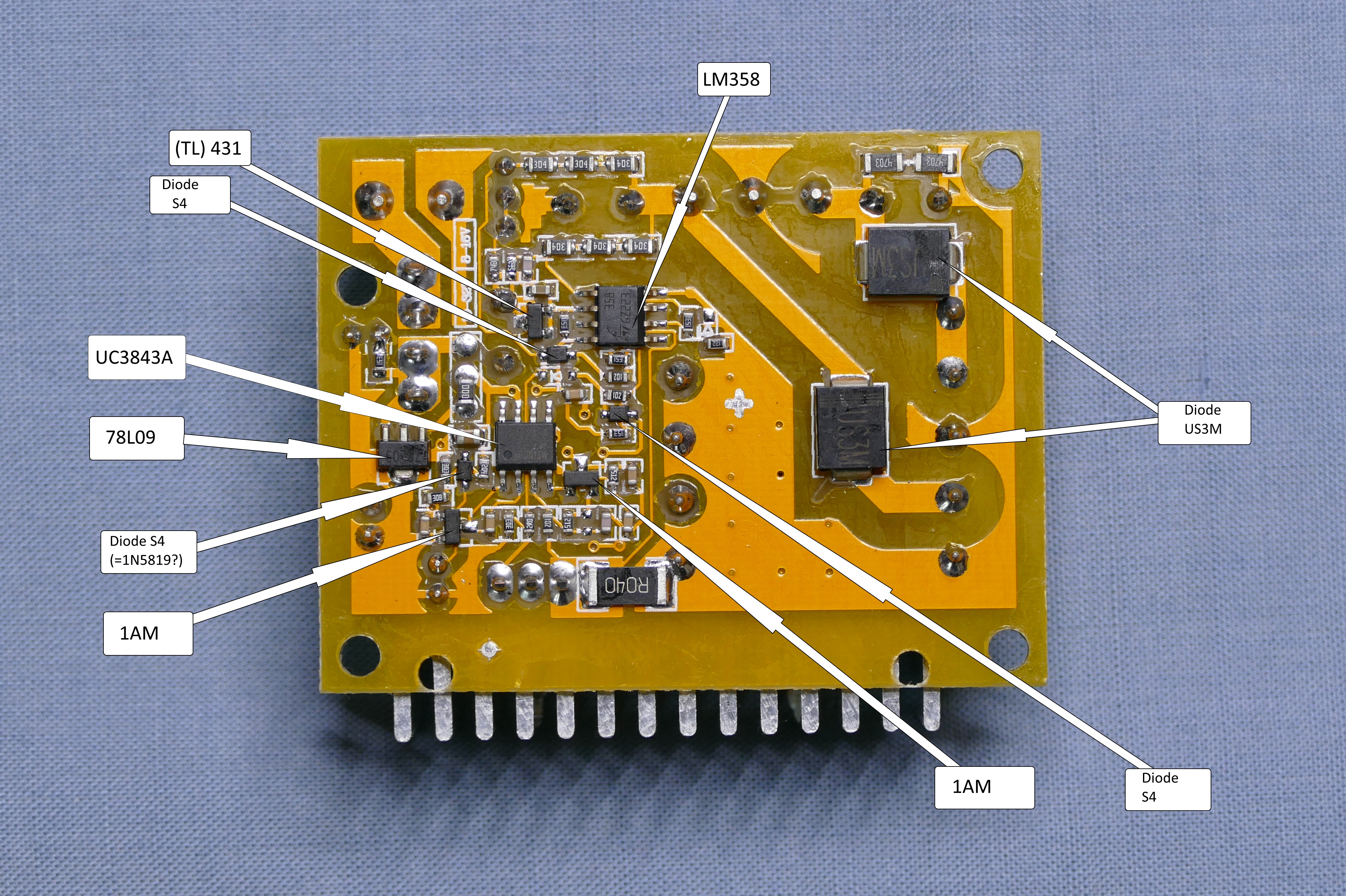
I can confirm that one chip is the UC3843, the other is an LM358 (labelled just 358). The 78L09 has been identified by others. There is also a 431 shunt regulator, possibly used in the HV feedback network. Two transistors 1AM (=LT1), two 1000V, 3A diodes US3M. At the moment I have not identified the smaller, mainly passive, components.
Give me a day or two and I will get out the camera and lights and I will mark up and post photos showing the actual position of everything on the board.
As promised herewith the picture of the components with the active ones marked.
The only active on the other side is the Mosfet RU7088 on the heatsink.
The only active on the other side is the Mosfet RU7088 on the heatsink.
Schematic? No. But it is simple boost, you could probably follow UC datasheet to get there. Trace it out, it's very simple circuit.Anyone have a schematic or working LTSpice simulation?
Or do you want something more specific?
Schematic? No. But it is simple boost, you could probably follow UC datasheet to get there. Trace it out, it's very simple circuit.
Or do you want something more specific?
I'm primarily interested in learning how this ZVS boost topology works.
This is not ZVS at all, why do you think it is?I'm primarily interested in learning how this ZVS boost topology works.
This is not ZVS at all, why do you think it is?
This module is advertised as ZVS all over eBay.
DC-DC Boost Converter 8-32V 12V to +-45V-390V High Voltage ZVS Board Module NEW | eBay
It is, but I think it's standard hard switching boost, not ZVSThis module is advertised as ZVS all over eBay.
DC-DC Boost Converter 8-32V 12V to +-45V-390V High Voltage ZVS Board Module NEW | eBay
It is, but I think it's standard hard switching boost, not ZVS
There must be 20 different China based eBay sellers selling the same module as ZVS. So much for truth in advertising!
Do you recommend another soft switching LLC ZVS reference boost to learn the topology? Secondary side power factor correction would be a bonus.
Cheers!
- Home
- Amplifiers
- Power Supplies
- YH11068A 10-32V to 45-390V dc/dc - guess the control ICs