I got an idea about a speaker & amplifier combination. I thought it would be wise to ask if others have experiment with this.
So my idea is to build a system with these features:
I got few questions also:
So my idea is to build a system with these features:
- Mark Audio Alpair 12P full range speaker drivers (two)
- Approximately 3 cubic feet or 85 litres sealed cabinets (two)
- Quite tightly muffled box cavity with plenty of teared cotton ribbons
- A current-drive made with a transconductance amplifier or by other means
- No other drivers or any passive filters
- Decent cables, nothing fancy
I got few questions also:
- Would the mechanical damping flatten the resonance enough or should I also prepare to build a filter to take care of that low frequency resonance?
- I thought about covering the speaker boxes with acoustic cloth (speaker grille cloth). The boxes are right-angled. I would cover each box with snugly fit cloth hoods. Anyone done this and does it work well?
[*]Approximately 3 cubic feet or 85 litres sealed cabinets (two)
Why the large "sealed" boxes?
[*]Would the mechanical damping flatten the resonance enough or should I also prepare to build a filter to take care of that low frequency resonance?
Where is this low frequency resonance?
jeff
Resonances, less resonances
According to Mark Audio Fo = 42 Hz. In an enclosure the frequency will be higher. Due to the acoustical damping I expect the impedance bump become much lower than 60 ohm.
Sealed because I don't want to introduce resonances, and so tightly damped sealed box is one obvious option. Also, as I said, I already have them. Making them bass reflex would be probably a small effort, but how would it work with the current-drive, that is questionable.Why the large "sealed" boxes?
Where is this low frequency resonance?
jeff
According to Mark Audio Fo = 42 Hz. In an enclosure the frequency will be higher. Due to the acoustical damping I expect the impedance bump become much lower than 60 ohm.
I doubt the cardboard box will cut it. With the current amp you want the impedance peak to be reduced as much as possible. And where it does rise ideally the box voltage driven is already rolling off.
I would build an aperiodic TL. The TL itself can reduce the peak a bit, the heavy aperiodic damping will take it further.
dave
I would build an aperiodic TL. The TL itself can reduce the peak a bit, the heavy aperiodic damping will take it further.
dave
Combination of aperiodic box and damping material
Aperiodic vent + plenty of damping material may be an option. If that flattens the resonance bump, that could be the trick I was looking for.
Aperiodic vent + plenty of damping material may be an option. If that flattens the resonance bump, that could be the trick I was looking for.
Sealed aperiodic TL
I am not sure should a sealed enclosure with an acoustic labyrinth inside be called as transmission line, but I may try that.
The whole point is in damping the system acoustically enough that you don't even think about dampen it more via back EMF.
I am not sure should a sealed enclosure with an acoustic labyrinth inside be called as transmission line, but I may try that.
The whole point is in damping the system acoustically enough that you don't even think about dampen it more via back EMF.
Attachments

Hi!A current-drive made with a transconductance amplifier or by other means
please give some more details on the amp you intented to use, maybe a link?
A half-wave (ie sealed) aperiodic TL is a real possibility in terms of getting the resonant peak down to make it suitable for a current amp.
A heavy taper allows it to be shorter, the B&W Nautilus is the poster child for this. Here a prototype:
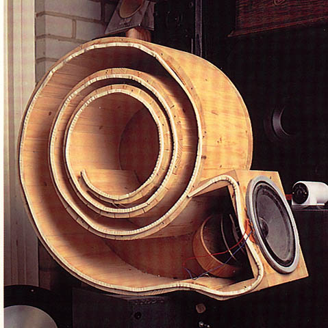
I used a similar idea (but quarter wave), aperiodic TL, to make a FR most suited to an OB (Visaton B200) work in a box.
dave
A heavy taper allows it to be shorter, the B&W Nautilus is the poster child for this. Here a prototype:
I used a similar idea (but quarter wave), aperiodic TL, to make a FR most suited to an OB (Visaton B200) work in a box.
dave
if the Fo = 42Hz , the Zmax should be around that point as opposed to 100 to 200hz.
from the graph I would guess the Fo = 140Hz
my Bad, FF85k is a small speaker I thought we were looking at the Alpair driver
from the graph I would guess the Fo = 140Hz
my Bad, FF85k is a small speaker I thought we were looking at the Alpair driver
Last edited:
The graph i posted earlier was for the 3” FF85k not the A12p. The intention was to show how an aperiodic TL can reduce the impedance peak,
dave
dave
A tapered sealed TL with variable stuffing from very loose at driver to tightly packed at small closed end works very well to flatten impedance peaks. TL doesn't have to be long - even 12in is sufficient to act as an acoustic black hole. This is basis of the Dagger TL. Dagger is a tall 3-sided pyramid. 3 sides prevent side to side reflection resonances. Gradually packed taper slowly absorbs sound like a Wood's horn, but for sound energy vs light absorption.
Dagger:
10F/8424 & RS225-8 FAST Ref Monitor
Dagger:
10F/8424 & RS225-8 FAST Ref Monitor
Answer to the amplifier question
Probably I would try the speaker with a conventional (ie. voltage feedback) audio amplifier and a series connected resistor. Just because that is a very quick way to proceed.
I suppose I like it, so next should be either a new amplifier or a combination of an audio transformer and a resistor.
If I choose to build a new amplifier, it may be a single-ended pentode with current feedback or perhaps some solid state design by Esa Meriläinen.
See:
Class-A power amplifier project | Current-Drive - The Natural Way of Loudspeaker Operation
Single-ended amplifier project | Current-Drive - The Natural Way of Loudspeaker Operation
However, because a new integrated amplifier would be quite a big project, I would probably choose the transformer and resistor combination. Then, perhaps later an amplifier.
Hi!
please give some more details on the amp you intented to use, maybe a link?
Probably I would try the speaker with a conventional (ie. voltage feedback) audio amplifier and a series connected resistor. Just because that is a very quick way to proceed.
I suppose I like it, so next should be either a new amplifier or a combination of an audio transformer and a resistor.
If I choose to build a new amplifier, it may be a single-ended pentode with current feedback or perhaps some solid state design by Esa Meriläinen.
See:
Class-A power amplifier project | Current-Drive - The Natural Way of Loudspeaker Operation
Single-ended amplifier project | Current-Drive - The Natural Way of Loudspeaker Operation
However, because a new integrated amplifier would be quite a big project, I would probably choose the transformer and resistor combination. Then, perhaps later an amplifier.
FWIW, I've driven many 'FR' drivers with [very] low DF amps and added an 8-10 ohm resistor to ~double Qts and the few done at DIY Meets long ago now were well received, so based on published specs, ~80 L will make a max flat sealed alignment that should only need minimal damping, though if you switch to a high output [matching] impedance amp, then ideally it will need the ~aperiodically damped TL or an impedance compensation network.
GM
GM
That current drive link is very interesting. I like SE Class A amps but prefer simple MOSFETs. You do realize that using a voltage regulator as the active device is like adding a 12 transistor op amp to the audio path.
Here is a really simple Class A mosfet follower:
Build This MoFo!
Here is a really simple Class A mosfet follower:
Build This MoFo!
Current drive technology is a necessary step to decrease distortion of sound reproduced by electrodynamic speakers.
Comparative Measurements on Loudspeaker Distortion: Current vs. Voltage Control | MERILAINEN | Archives of Acoustics
Comparative Measurements on Loudspeaker Distortion: Current vs. Voltage Control | MERILAINEN | Archives of Acoustics

- Home
- Loudspeakers
- Full Range
- Mark Audio Alpair 12P with current drive