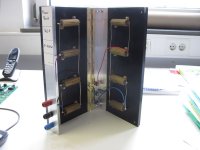
For years I've been using a wirewound resistor with some leads and banana plugs as a dummy load for testing amps.
I thought I would buy a proper one but I couldn't find anything pre-made (MCM used to sell one...)
So in case anybody is looking for ideas, here is what I made:


More details here: Audio Dummy Load
The chassis came from Landfall Systems, the extrusion from Heatsink USA, and the resistors (a bargain) at Surplus Sales of Nebraska.
Pete
I thought I would buy a proper one but I couldn't find anything pre-made (MCM used to sell one...)
So in case anybody is looking for ideas, here is what I made:
More details here: Audio Dummy Load
The chassis came from Landfall Systems, the extrusion from Heatsink USA, and the resistors (a bargain) at Surplus Sales of Nebraska.
Pete
Very nice ! I like it, and it prevents burns from dangling hot resistors.
You _could_ use some of the signal , rectify in a bridge and feed a 12V fan
for elongated runs .
You _could_ use some of the signal , rectify in a bridge and feed a 12V fan
for elongated runs .
Three or four years ago I found some 100W 8 ohm dummy loads at parts express, I believe. My setup sure doesn't look as good as yours. HeyBill
I still use Dale NH-250-8 that
I purchased from sound technology for $20 each many many years ago.
Art
I purchased from sound technology for $20 each many many years ago.
Art
Don't forget the oil filled radiator electric heaters. They often have heating elements in the 8R-9R range and can soak up a LOT of power.
For years I've been using a wirewound resistor with some leads and banana plugs as a dummy load for testing amps.
I thought I would buy a proper one but I couldn't find anything pre-made (MCM used to sell one...)
So in case anybody is looking for ideas, here is what I made:
More details here: Audio Dummy Load
Pete
Thank you for this.
In your linked article drawing "red and "black" seem to be interchanged.
I found it useful to add a small series resistor in the wire to the "hot" inner pole of the RCA socket for safety.
Some people may find it useful to have these monitor jacks floating from ground, with 1:1 signal transformers,
to avoid shorts on the scope common ground input with bridged power amp outputs (many Class D and some
OTL amps). The signal purity will be impaired of course, so I use a set of these transformers separately.
Rather than the 12 ohms position I use an "infinite" or no load position. This can be done with some types of
three position toggle switches. Useful for quick checking the damping without calculation and of great value
during power amp repair..
An additional resistor / potentiometer set will allow connection of a small monitor speaker or even headphones.
Just a small suggestion from a plain engineer ..
Last edited:

Repurpose BOSE 2 stanalone amplifier
Bose Lifestyle SA2 basically a heatsink with an amplifier in it. lots being thrown away.
(Bose Lifestyle SA3 are useful because they can be used as stanalone amplifers, which I have for my car porch)
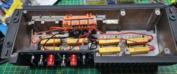
Totally based on Petes design so thank you Pete.
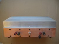
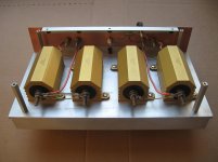
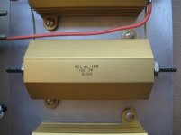
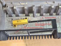
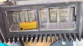
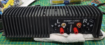
I implemented a 4/6/8Ohm Dummy load using 50W 4Ohm resistors. they are screwed to the top slighly curved surface, so I used 1mm thick thermal pad (Gelid Solutions GP-Ultimate)
I used my 3D printer to print tempates for the cut out & the holes, Fins are 38mm centres, resistors I used were 40mm, hence on a slant. 1mm Thermal pad visible all around.
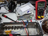
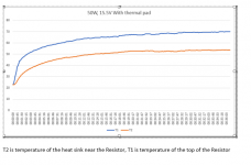
(I did check that the pads would work with the resistor & heatsink. See graph after 36 minutes)
Bose Lifestyle SA2 basically a heatsink with an amplifier in it. lots being thrown away.
(Bose Lifestyle SA3 are useful because they can be used as stanalone amplifers, which I have for my car porch)
Totally based on Petes design so thank you Pete.
I implemented a 4/6/8Ohm Dummy load using 50W 4Ohm resistors. they are screwed to the top slighly curved surface, so I used 1mm thick thermal pad (Gelid Solutions GP-Ultimate)
I used my 3D printer to print tempates for the cut out & the holes, Fins are 38mm centres, resistors I used were 40mm, hence on a slant. 1mm Thermal pad visible all around.
(I did check that the pads would work with the resistor & heatsink. See graph after 36 minutes)
Attachments
-
 BoseResistorHoles1_a.jpg310.1 KB · Views: 265
 -
 BoseFaceplateCutout1_a.jpg415.2 KB · Views: 249
 -
 BoseFinalBuild3.jpg673.7 KB · Views: 326
 -
 BoseFinalBuild2.jpg844.8 KB · Views: 326
 -
 BoseFinalBuild1.jpg860 KB · Views: 338
 -
 BoseResistorTest.jpg838.4 KB · Views: 361
 -
 4Ohm50WResistor with ThermalPAd on Bose2.PNG48.1 KB · Views: 267
Last edited:
Bose Lifestyle SA2 basically a heatsink with an amplifier in it.
😀 this is ingenious and hilarious at the same time! I need one.
stl files of faceplate and templates
When I get a moment I'll put stl files up on prusaprinters for faceplate and templates.
BTW I have a spare Bose SA2, that i'll send with templates and faceplate for £20 delivered, only to UK. SA2 will be empty to save on postage costs.
When I get a moment I'll put stl files up on prusaprinters for faceplate and templates.
BTW I have a spare Bose SA2, that i'll send with templates and faceplate for £20 delivered, only to UK. SA2 will be empty to save on postage costs.
Last edited:
As a stereo dummy I use the "Power Book, Vol1", a re-issue of Ohms Law.😉
Excellent! I love it 😎
Jan
BTW I have a spare Bose SA2, that i'll send with templates and faceplate for £20 delivered, only to UK. SA2 will be empty to save on postage costs.
I'd snap that up if still available. BTW also in Cambridge UK, so can even saving you the hassle of posting the bloody thing.
Do you have BOM for the other bits? I can order them or similar.
1st come 1st served.
£15 if your picking up. I'll pm you
I'd snap that up if still available. BTW also in Cambridge UK, so can even saving you the hassle of posting the bloody thing.
Do you have BOM for the other bits? I can order them or similar.
£15 if your picking up. I'll pm you
- Home
- Amplifiers
- Tubes / Valves
- Audio dummy load