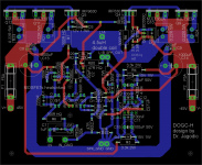
Hi, I have made PCB layout in Eagle 6.5 for DOGC-H amplifier designed by Dr. Borivoje Jagodic.PCB is not tested yet, so any improvement suggestions are welcomed.
Can you post a .pdf of the board?
JFETs input
Hi,
what about using JFETs in LTP instead of mosfets? It should sound better, right?
Anyone here interested and skilled enough to design DOGC-H with JFETs LTP?
Hi,
what about using JFETs in LTP instead of mosfets? It should sound better, right?
Anyone here interested and skilled enough to design DOGC-H with JFETs LTP?
Is this the DOGC-H that you've built? I am interested in making one of these but I have a chassis with +- 36v rails and I'd like to stay with H version to drive 4 ohm loads reliably. I'd also be interested in someone with some design nouse to comment on the implications of jfet input vs mosfet. I'm also interested in the current boosting diodes that Nelson Pass has added in the F5 turbo and what might stop those being added to any old design.. (like, say, this one!) Since they appear to offer opportunity for basically doubling the available current from a given design if there's an adequate power supply.
Was there any matching of devices involved? Are there build threads in English for this clever design? I'd love to have a Quad 606 but the complexity of the DOGC-H build looks potentially more my speed!
Was there any matching of devices involved? Are there build threads in English for this clever design? I'd love to have a Quad 606 but the complexity of the DOGC-H build looks potentially more my speed!
Last edited:
Is this the DOGC-H that you've built? I am interested in making one of these but I have a chassis with +- 36v rails and I'd like to stay with H version to drive 4 ohm loads reliably. I'd also be interested in someone with some design nouse to comment on the implications of jfet input vs mosfet. I'm also interested in the current boosting diodes that Nelson Pass has added in the F5 turbo and what might stop those being added to any old design.. (like, say, this one!) Since they appear to offer opportunity for basically doubling the available current from a given design if there's an adequate power supply.
Was there any matching of devices involved? Are there build threads in English for this clever design? I'd love to have a Quad 606 but the complexity of the DOGC-H build looks potentially more my speed!
Hi,
I have built DOGC-H with mosfets input as in original schematics. It is good idea to match input mosfets and I matched them. You could also match output BJT transistors, but I think it is unnecesary.
I think JFET input should sound better, but they hard to find and you need to cascode them in this design. Even with mosfets input the amplifier sounds superb to me (better than Symasym which I have built too), definately recommended.
I attach my latest PCB design for DOGC-H. Done in Eagle.
Attachments
Thank you for this! What voltage rails did you use? Mostly I see that tweaking is necessary for most designs (for bias etc) when the rails change, and I'm not clever enough to do that. I recall that the designer himself has helped people with regard to adjusting his design to suit various requirements, though I imagine someone may have done it (made with close to 36v rails) already since it seems a popular design in its home country.
All the best from Australia! 8)
All the best from Australia! 8)
Thank you for this! What voltage rails did you use? Mostly I see that tweaking is necessary for most designs (for bias etc) when the rails change, and I'm not clever enough to do that. I recall that the designer himself has helped people with regard to adjusting his design to suit various requirements, though I imagine someone may have done it (made with close to 36v rails) already since it seems a popular design in its home country.
All the best from Australia! 8)
I have made two amplifiers. One with +-45V rails and other with +- 35V. In DOGC design you do not have to tweak anything when changing voltage of rails. But I wouldn´t go lower then +-35V.
..thx for sharing! (the Target3001 file is in the attachement)
Attachments
Last edited:
I have built Dogc-h, and have question, how many current must flow thru IRF9630/630. I have almost 220mA, and i'm wondering if its correct, sinus looks also good.
On DOGC-MK3 IRP9530/530 its 330mA, and it's similar design.
On DOGC-MK3 IRP9530/530 its 330mA, and it's similar design.
DOGC-H is about 220mA. It is lower than DOGC-MK3 becuase of higher voltage rail - 48V vs 40V. So to keep dissipation circa same.
I have a problem with burning input mosfet, Irfd110. It happend 2 times, every time when turning on amplifier. Do you think that gate/drain capacitor is to low, 220pF, and thats why its oscilate and get burned?
I believe that you somehow induced static electricity to an input, similar had happened to me. I had trouble with poor main ground connections so I had low current but about 120Vac. gates of mosfets are very sensitive to voltage higher than Vgs max given in devices characteristics (usually not more than 15V).
when I solved problem with mains ground contacts, I have repaired dogc and it works all right since than (more than four years now).
first find source of problem and than repair and connect your amplifier.
when I solved problem with mains ground contacts, I have repaired dogc and it works all right since than (more than four years now).
first find source of problem and than repair and connect your amplifier.
My amplifier was working and tested, it happends random, not always when im turning on amplifier. Amplifier has been operating for 3 months, and from that moment it has already been burned twice, in november and now.
Last edited:
Hmm
I wonder so, my power supply is 2x37ac (old trafo on 220V), sometimes its +- 53Vdc. AC lines can show 223-234Vac. Irfd110 has Vds100V, can it be the reason of burning?
I wonder so, my power supply is 2x37ac (old trafo on 220V), sometimes its +- 53Vdc. AC lines can show 223-234Vac. Irfd110 has Vds100V, can it be the reason of burning?
- Home
- Amplifiers
- Solid State
- DOGC-H by Dr. Jagodic