Just wanted to know if anyone experienced such bad clipping behavior,
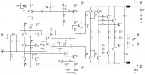
The circuit is a blameless with enhanced vas.
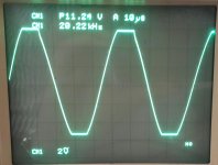
The really bas waveform is without diode D8.
Does anyone have a suggestion as to any changes to improve clipping.
The circuit was just built so many changes to make.
Thanks
The circuit is a blameless with enhanced vas.
The really bas waveform is without diode D8.
Does anyone have a suggestion as to any changes to improve clipping.
The circuit was just built so many changes to make.
Thanks
Attachments
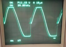
the shape of the behavior looks about as good as it gets. Is there a 10X factor missing on the scope display for amplitude? the legend implies 2V/box, but the amp's rails look like it should deliver much more swing before clipping.
The digital display on top showing ch1 P11.24V is peak to peak using a x10 Probe.
Giving a 56V peak output.
Giving a 56V peak output.
Just wanted to know if anyone experienced such bad clipping behavior,
What you see on the scope is the VAS transistors getting saturated on negative clipping. When coming out of clipping it takes a long time to un-saturate them, which is why the output stays stuck on the negative rail. The diode prevents saturation of VAS transistors, making recovery quicker.
2 things ...
Why run the CCS at high current ? As well as it also saturating during clip ,
it makes the active half of the VAS "misbehave" more so.
You have a triple EF , 3-5ma VAS I is plenty enough and will run cooler-
less heat and distortion.
10R (R20) as the active VAS Re does not allow Q19 to clamp saturation. With
CM/beta enhancement .. you don't need that low of a Re , try 100-150R instead.
Loop gain of this amp is already high , if you need more .... lower Re on the
LTP or CM instead.
OS
The circuit showed original values, but to reduce bad clipping changed R2 and R4 to see if it changed things, it didn't.
The photos above is with the circuit posted but with the R2 = 180R increasing input current to LTP to about 3.5mA shared into two.
The photos above also have the VAS ccs resistor R4 = 82R decreasing current to about 8mA.
I'll increase VAS Re to 27R and then 47R and see how clipping behaves at 8mA VAS current.
Ill decrease VAS current to 4mA and do the same looking at clipping.
Regards
This still has some 'overhang' Pavel, but I would agree its better than the single ended blameless design in this regard.
I used diodes on my symetrical e-Amp and distortion is <10ppm 20 kHz at 180W. You need to use a low capacitance diode. Without the diode, I get another 2-3ppm lower distortion - not a problem in the big scheme of things.
Having said that, I agree with OS's proposals, altthough I like to run my VAS at about 20mA in a triple 😉
Interestingly, I've noticed that this is much less of a problem on CFA's - I commented about it in the sx-Amp write-up.
Richard, now you see why we think how an amp behaves when it clips is important!
Some good inputs from GK there. Notice how he runs the LTP and the VAS CCS separately. The other option is to increase the base resistors from the 47 Ohm you show to a few k (you will get more noise) - this will mean when the CCS saturates, you pump less excess current into the base.
I'd increase the emitter load resistance on the helper transistor to a few k. I typically use 4k7 - you really dont need 820 Ohms. Drop the helper transistor collector resistor. Again, if you drive this hard into clipping, this will saturate, and you have problems.
Glen uses two back to back diodes across the mirror, and a helper transistor as well. Mirror recovery from saturation is also notorious.
only reason for using 820R was to settle on a 1mAq though transistor
The boards are made, if i would make another version, I would split the CCS for input and VAS
From simulation only, it seems like the diode clamp relieves the first (smaller) transistor during clipping.
It seems that with diode clamp in place that I can get away with replacing collector resistor (560R) in first vas transistor with a link.
What are you thoughts
Last edited:
Removing 560 Ohms wouldn't be a problem for normal operation.
In the abnormal condition of the amp being driven while the collector of the driver transistor was faulted to ground, the diode couldn't protect the first transistor. But then, you can't protect against everything.
In the abnormal condition of the amp being driven while the collector of the driver transistor was faulted to ground, the diode couldn't protect the first transistor. But then, you can't protect against everything.
Whst about the 47 ohm resistors in the CCS bases? I would raise these as well.
But, before you do that, see how it behaves after you link the helper collector resistor out, and increase the helper emitter resistor.
Hopefully it will be much cleaner on the negative swings, and the you can focus on the positive clipping.
But, before you do that, see how it behaves after you link the helper collector resistor out, and increase the helper emitter resistor.
Hopefully it will be much cleaner on the negative swings, and the you can focus on the positive clipping.
Beware, diode connected as this dramatically increases THD.
Not if it is a VERY low reverse leakage type.
pA/nA leakage can be corrected by NFB - uA can not be.
But , even the best diodes will add 5-10ppm at moderate amplitude -
a "tradeoff".
OS
Notice how he runs the LTP and the VAS CCS separately.
No , forgot about that thread , all the "flaming" 😀 ...
I must of held it in my sub-conscience , my wolverine splits the CCS's.
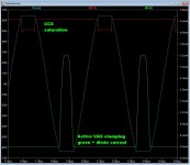
With either the diode or active clamp , the VAS CCS still saturate's slightly.
Kept the option for diode or transistor clamping in my PCB.
Many models , either technique - I get (below 1)
CCS still saturates slightly , but not "badly".
Top of waveform has a minute "sticking" due to the VAS CCS saturation,
bottom still has the slight "fold" in the middle before the diode can clamp it.
But it is a hell of a lot better than without.
The transistor technique needs a fast device with 1k basestopper and some
"Re on the VAS" to work with.
Still single digit PPM with both techniques. (below 2 ) Lost 2-3ppm 🙁 .
Boooo ...hooo 😀
OS
Attachments

- Home
- Amplifiers
- Solid State
- bad clipping