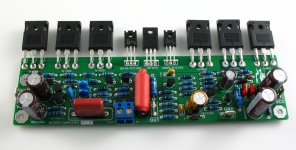
This is my new design of a level after amplifier.
It adopted VISHAY company produces the IRFP240 MOSFET. Each track six only.
This is a focus on low distortion of amplifiers, circuit structure asymmetrical sent fraction circuit. And must complementary structure.
After several times of modification and test. Main improvement is the reliability problems.
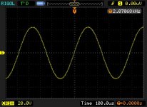
Now output can achieve + 65 V sine wave and good work.
It adopted VISHAY company produces the IRFP240 MOSFET. Each track six only.
This is a focus on low distortion of amplifiers, circuit structure asymmetrical sent fraction circuit. And must complementary structure.
After several times of modification and test. Main improvement is the reliability problems.
Now output can achieve + 65 V sine wave and good work.
Attachments
PCB is good but can we see a schematic?
Can. But I hope that this circuit is used only for reference. Because of the different parts will have to change some of the circuit structure.
I try to use different parameters.
In addition. The circuit structure similar to MK2 mosfet amplifier.
Attachments
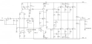
I think Q11 is connected in wrong way on the schematic isn't it ?
Sorry. Because I use of the pipe and software packages of different, just to from already the design is convenient.
In fact is different.
Can. But I hope that this circuit is used only for reference. Because of the different parts will have to change some of the circuit structure.
I try to use different parameters.
In addition. The circuit structure similar to MK2 mosfet amplifier.
Ok this is quasicomplementary circuit, did you in your amp test symmetrical clipping ?
often quasicomplementary amps dont have symmmetrical clipping
Transistor Q20 is good solution, did you test this amp in real load condition and is it stable working ?
Did you make this board is it the the final revision?
Is there already a place to get them?
Is there someone selling these LJM designs on ebay?
Is there already a place to get them?
Is there someone selling these LJM designs on ebay?
Last edited:
Pretty similar to the last mosfet amp i made, only major diff is the "upside down" PNP LTP. Transistor Q20 seem to serve the same function as the baxandall diode.
I had the same number of mosfets but got 214 watts continous unclipped into 4 ohms.
I had the same number of mosfets but got 214 watts continous unclipped into 4 ohms.
Pretty similar to the last mosfet amp i made, only major diff is the "upside down" PNP LTP. Transistor Q20 seem to serve the same function as the baxandall diode.
I had the same number of mosfets but got 214 watts continous unclipped into 4 ohms.
Dis you design it? Have you got any info on it?
Ok this is quasicomplementary circuit, did you in your amp test symmetrical clipping ?
often quasicomplementary amps dont have symmmetrical clipping
Transistor Q20 is good solution, did you test this amp in real load condition and is it stable working ?
The front part of the amplifier to continue the DOUGLAS no defects amplifier. Is a very low distortion of the AMP, I had been used in ordinary transistor.
The back of the output type must complementary mosfet is common design. Different resistance and transistor type can change LPF of IQ, and stability,.
The amplifier once in test version met so many problems.
I have to say more trouble than the BJT use MOSFET.
After four or five times after the revision of the amplifier, connected to the speaker for load in under the conditions of the test.
And very stable strong. And then I use a pair of speakers in the UK as the feeling after the audition FB1 PMC contractor.
His voice from the performance is excellent. And it's very easy to amateur installation.
Did you make this board is it the the final revision?
Is there already a place to get them?
Is there someone selling these LJM designs on ebay?
B: yes. My amplifier is some dealers to sell on the EABY.
I have nothing against.
The letter called L is limited to the amplifier.
L6 L12 L20 and this type of L 150 W. They are in China is the most popular AMP.
quasis mosfet amp works really good, hard to beat
B: yes. Also this circuit in comparison to ordinary BJT.
It appears some not good phenomenon.
Such as square wave appear overshoot phenomenon.
And for a ZOBEL, or the capacitive load of the great instability.
I through the advanced compensation, and output RL network to refrain from this phenomenon.
These simple method is practical and effective.
fter adjustment, the performance of the MOSFET advantage is also very good.
It can be very easy to use, the condition in high power mosfet is the power consumption and current can be sufficient.
It can be very easy to output large current, but they don't need too much current input class G.
So it can work in a very rigorous condition.
It can be very easy to use, the condition in high power mosfet is the power consumption and current can be sufficient.
It can be very easy to output large current, but they don't need too much current input class G.
So it can work in a very rigorous condition.
Heres a high power version of the one i was doing some months back:
http://i.imgur.com/ylBAl.png
Q11 / mje 340 parallel with 470R .... do you have symmetrical clipping ?
do you use heatsink for Q11
my quasi nmos have array from 3 x 1n4148 parallel with 33nf and 56R
Last edited:
This is not built yet. but it should be capable of up to 900W peak short term and around 300w continous into a 4 ohm load using a 2x48v 500va transformer.
Q11 / mje 340 parallel with 470R .... do you have symmetrical clipping ?
do you use heatsink for Q11
my quasi nmos have array from 3 x 1n4148 parallel with 33nf and 56R
Similar to 5551. Just feet a somewhat different.
- Home
- Amplifiers
- Solid State
- New Design L 150W FET Amplifier