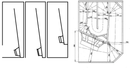
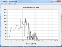
Image 1 contains four drawings.
1 and two are basically the same thing but with the mouth on the side or what should be the top (that should be flipped upside down). In either case the mouth is the same distance from the back driver tap within a few mm, and the back driver tap is about as close to the mouth as you can get.
The 3rd drawing is almost the same thing with an extra fold to put the back side driver tap a bit further back from the mouth.
The 4th is a random pic of the XOC TH18 google grabbed from one of the threads, showing the driver as close to the mouth as you can get.
A lot of early diy tapped horns were like the first two examples, It's easy to fold and build, very forgiving if you place the middle baffle at an angle that's not quite right and it's a good shape for domestic use, a large volume with a tiny footprint.
The problem with these is the dip in the response right before the big peak can be nasty. And I don't know how people that built these feel about it or deal with it. Personally I now have an amp with Audyssey so that's my only eq. I don't think any pre programmed eq system is going to touch a 10 db dip with a ten foot pole. I think they look at it like a black hole, no matter what you throw at it you can't fill it so there's no point in even trying. And that thing is always right at the edge or right outside the passband where even a steep low pass crossover isn't going to hide it.
There's a bunch of things you can do to fill it a bit. You can move the driver back a bit from the mouth but then folding complexity skyrockets.
You can make the horn bigger. Somewhere on the way to the size of a garden shed the frequency will even out at a level around the top of the harmonic peaks.
You can do dual or even triple different flare rates the the XOC TH18 to move the resonances causing that dip in a way that lessens the issue, but folding complexity skyrockets.
You can increase the compression ratio. A very high compression ratio can fix that dip right up, at about 4:1 the dip fills in completely in this example horn but the entire response looks overdamped if you do that, kind of what it looks like with a weak magnet.
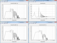
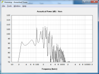
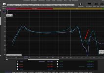
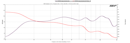
Image 2 contains 4 Hornresp screen grabs.
1. Light trace - A single PAR flare rate 470 liter tapped horn, 18TBW100 at about 27 cm from both the throat and mouth, this corresponds to Image 1 drawing 1 or 2.
Dark trace - Same thing with the mouth side tap moved back to 68 cm. This reduces the big dip from about 7 db down to maybe 1.5 db.
2. Top row right - This shows group delay for the same examples described above. Notice group delay is better on the one with the worse response dip.
3. Bottom left - Hornresp suggest that putting these horns in a corner or using them in multiples fills in the dip on the left side of 100 hz spike a bit but makes the dip on the right side of the peak worse. This is good information because I will be using a tapped horn in a corner so it's something to keep an eye on but for the tapped horn with the driver side tap close to the mouth, the dip only filled in a couple db. It's still a gaping 5 db hole.
4. Bottom right - That's the XOC TH18 (it's one of the iterations, I don't know which one) with the same driver I used in the other sims shown here just to keep it apples to apples. Despite having the driver so close to the mouth it almost looks like it's trying to escape, that tiny little dip is the result of the dual flare rate in that horn. If you change it to a single flare rate it turns into a 5 db hole, which isn't as bad as the 7 db hole shown in the other example here but that's probably because it's tuned much much higher and the impedance peaks in different places.
Does anybody know how Audyssey handles big dips?
How big is too big in your opinion? At what point is the fold complexity and group delay worth the trade off of a smaller dip?
I don't like to go too far below 2:1 compression ratio, the XOC TH18 sim I found doesn't, generally Danley doesn't, although he famously did in the actual TH118. What are your thoughts on that?
Any other general thoughts on anything?
I got an itch to build something. I was going to do a dirt simple single fold tapped horn like the first example in image 1, something quick to shake the rust off because it's been a long time. Then because of the dip I was going to do example 3. And now I figure if I'm going to have to live with the damn thing maybe I need to a a much larger lower tuned version of the TH18. (That doesn't already exist by the way, does it? I haven't been around for awhile. I need 25 hz or lower tuning.)
Thanks.
1 and two are basically the same thing but with the mouth on the side or what should be the top (that should be flipped upside down). In either case the mouth is the same distance from the back driver tap within a few mm, and the back driver tap is about as close to the mouth as you can get.
The 3rd drawing is almost the same thing with an extra fold to put the back side driver tap a bit further back from the mouth.
The 4th is a random pic of the XOC TH18 google grabbed from one of the threads, showing the driver as close to the mouth as you can get.
A lot of early diy tapped horns were like the first two examples, It's easy to fold and build, very forgiving if you place the middle baffle at an angle that's not quite right and it's a good shape for domestic use, a large volume with a tiny footprint.
The problem with these is the dip in the response right before the big peak can be nasty. And I don't know how people that built these feel about it or deal with it. Personally I now have an amp with Audyssey so that's my only eq. I don't think any pre programmed eq system is going to touch a 10 db dip with a ten foot pole. I think they look at it like a black hole, no matter what you throw at it you can't fill it so there's no point in even trying. And that thing is always right at the edge or right outside the passband where even a steep low pass crossover isn't going to hide it.
There's a bunch of things you can do to fill it a bit. You can move the driver back a bit from the mouth but then folding complexity skyrockets.
You can make the horn bigger. Somewhere on the way to the size of a garden shed the frequency will even out at a level around the top of the harmonic peaks.
You can do dual or even triple different flare rates the the XOC TH18 to move the resonances causing that dip in a way that lessens the issue, but folding complexity skyrockets.
You can increase the compression ratio. A very high compression ratio can fix that dip right up, at about 4:1 the dip fills in completely in this example horn but the entire response looks overdamped if you do that, kind of what it looks like with a weak magnet.
Image 2 contains 4 Hornresp screen grabs.
1. Light trace - A single PAR flare rate 470 liter tapped horn, 18TBW100 at about 27 cm from both the throat and mouth, this corresponds to Image 1 drawing 1 or 2.
Dark trace - Same thing with the mouth side tap moved back to 68 cm. This reduces the big dip from about 7 db down to maybe 1.5 db.
2. Top row right - This shows group delay for the same examples described above. Notice group delay is better on the one with the worse response dip.
3. Bottom left - Hornresp suggest that putting these horns in a corner or using them in multiples fills in the dip on the left side of 100 hz spike a bit but makes the dip on the right side of the peak worse. This is good information because I will be using a tapped horn in a corner so it's something to keep an eye on but for the tapped horn with the driver side tap close to the mouth, the dip only filled in a couple db. It's still a gaping 5 db hole.
4. Bottom right - That's the XOC TH18 (it's one of the iterations, I don't know which one) with the same driver I used in the other sims shown here just to keep it apples to apples. Despite having the driver so close to the mouth it almost looks like it's trying to escape, that tiny little dip is the result of the dual flare rate in that horn. If you change it to a single flare rate it turns into a 5 db hole, which isn't as bad as the 7 db hole shown in the other example here but that's probably because it's tuned much much higher and the impedance peaks in different places.
Does anybody know how Audyssey handles big dips?
How big is too big in your opinion? At what point is the fold complexity and group delay worth the trade off of a smaller dip?
I don't like to go too far below 2:1 compression ratio, the XOC TH18 sim I found doesn't, generally Danley doesn't, although he famously did in the actual TH118. What are your thoughts on that?
Any other general thoughts on anything?
I got an itch to build something. I was going to do a dirt simple single fold tapped horn like the first example in image 1, something quick to shake the rust off because it's been a long time. Then because of the dip I was going to do example 3. And now I figure if I'm going to have to live with the damn thing maybe I need to a a much larger lower tuned version of the TH18. (That doesn't already exist by the way, does it? I haven't been around for awhile. I need 25 hz or lower tuning.)
Thanks.
Attachments
Last edited:

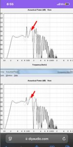
Move the other side of the driver father away (in another resonator) ? The phase is extended as that full wavelength is no longer the culprit/cancelation.
Here’s a 240 cm ‘tapped pipe’ (CSA doubles at 2/3 in a step/fold) with and without an added 80 cm resonator in parallel (like a folded bose wave cannon) .
It’s a bit overdamped at Fb, I could/should have used a larger crossectional area, and it’s Fb is only just below 40hz in this case .
(Red verses green in the last pic)
Just an idea, the gain and clean bandwidth/crossover region was a nice surprise when I finally measured some of this stuff
Attachments
These are associated with each other (and a lot of group delay created as well) ?
The upstream section shares that as a harmonic interval (‘7/4 resonace maybe?) . Drivers sitting in a pressure node on both sides and it’s audibly weird/unique in that area
The upstream section shares that as a harmonic interval (‘7/4 resonace maybe?) . Drivers sitting in a pressure node on both sides and it’s audibly weird/unique in that area
Attachments
Josh Ricci's Othorn is ~28Hz Fb, the Gjallerhorn ~16 Hz, both with twisty, hard to build paths similar to the TH18.And now I figure if I'm going to have to live with the damn thing maybe I need to a a much larger lower tuned version of the TH18. (That doesn't already exist by the way, does it? I haven't been around for awhile. I need 25 hz or lower tuning.)
https://data-bass.com/systems/5b11c15751412e00047d669d
Neither have any dips below 100Hz.
The Othorn has less upper ringing.
Art
Thank you sir. I'm aware of Ricci's tapped horn designs, I don't care for them personally. He does a good job of getting some great power density out of tiny designs but I don't like the compromises. First, he uses drivers I can't afford and second his designs look massively overdamped.
TLDR - I don't care for overdamped designs. Added resistance (like power compression) makes the frequency response curve shape of overdamped designs much much worse. In underdamped designs it actually gets better. That's basically the point and you can stop reading now. But if you want the long version here it is.
Here's a look at Othorn using Ricci's own Hornresp inputs. Not shown are the impedance and displacement graph. Both line up fairly well with the measurements, the bottom two measured impedance peaks are a couple hz higher than predicted by Hornresp and Hornresp has the displacement minimum (tuning) at about 29 hz.
But if you look at the response curve shape of the measured response vs the Hornresp prediction, the real world sub is much more overdamped than the sim. I don't have time to research how accurately the sim matches the fold but let's assume he did a good job translating the sim into the design he ended up building. And I have seen this a lot in different designs, especially the ones that are well damped to begin with, once folded, built and measured, they look more overdamped than the sim.
For now my working assumption is that mdf and plywood are not infinitely rigid, they impose losses on the real world design that do not exist in simland, real world impedance peaks are not as strong as simulated and the design becomes slightly more damped than predicted. This would happen to all designs but it's much easier to see in designs that are already fairly damped in the sim.
And it only gets worse from there. If you add a bit of Rg (series resistance) which could approximate the effects of the resistance of speaker wire, a less than perfect speaker wire connection, or especially thermal compression, things can get really ugly.
In the first attachment top row we have Othorn Hornresp inputs and schematic.
Lower left image bold trace shows Othorn predicted response. Notice the curve shape is already not even close to the low voltage measurement on his website that you posted. The light grey trace overlay shows what happens when you add Rg equal to Re. The low knee rises several hz and you get a 5 db saddle above it.
Lower right image shows a different tapped horn, a much more underdamped design. It's much more similar to the TH SPUD copies which were some of the first built and measured tapped horn designs. For an example look at the Hornresp sims of this clone. https://volvotreter.de/projects/th-2/the-tangband-cinema-sub-tapped-horn/ Since this was the one of the only built and measured diy tapped horns at the time and it was close to a Danley design, I made a tapped horn with similar undamped characteristics. The sim in the lower right panel of the first attachment is the design I built.
Notice that this design is wildly underdamped compared to the Othorn sim. And notice when you add Rg equal to Re the tuning goes DOWN, not up, and the overall response curve shape stays relatively usable.
If you add enough Rg the frequency response curve will melt down and have peaks exactly at the same spot as the impedance peaks. That's what you see happening in both these examples, but for some reason I'm not aware of, if the design is already overdamped like the Othorn, the lowest impedance peak (which would be aroumd 17 hz in Othorn) just isn't strong enough to keep the low knee in place. In an underdamped design like the one I built the lowest impedance peak does not disappear.
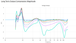
I've been told this added Rg example is extreme, it would never happen in the real world. But it did. Ricci measured this exact thing in the Othorn at his highest power sweep. See the second attached picture. The highest power sweep has the exact same curve shape as the added Rg sim I showed. The low knee rises several hz and there is a several db saddle right above it. See the third attached image to make it even more clear, this is the compression magnitude alone. It shows the same 5 db saddle the sim predicted.
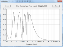
I've been told that the highest compression sweep is extreme, it would never happen in real life. I've been told Ricci's several second sweep methodology is extremely punishing. The Othorn writeup says the highest power sweep would put 4300 watts into the impedance minimums. Let's examine that. Even in a sweep that lasts several seconds the impedance minimums are only going to be lit up for very very short periods of time.
Ricci's sweep methodology is extreme compared to an input signal like an acoustic folk band, where the only real bass is a kick drum spike every second or so. BUT Ricci's sweep is extremely weak though, if you compare it to an EDM track that has a three minute long continuous sine wave at the exact frequency of the lowest impedance minimum. On the Othorn that would be at the 29 hz tuning in the sim. See attachment 4 for Othorn driver power at xmax.
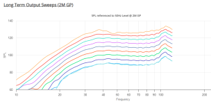
As per data-bass testing methods section, the long term output sweeps are 23 seconds long. If you look at attached image 4, the power peaks though the sweep frequency range are only maximally excited for a fraction of a second during a 23 second sweep, the rest of the time the applied power is some fraction of that. Also the 4300 watts that "momentarily" was applied at the impedance minimums for a fraction of a second isn't really 4300 watts, as he says himself, due to impedance rise. The thermal issues that are causing the response curve shape to shift at higher power are the result of increased impedance. When you increase impedance you draw less power.
So compare that 23 second long sweep that everyone says is brutal, in which the driver gets very high power for fractions of a second to an EDM track that has a constant (or at least persistent and extended) drone right at the box tuning, which is the impedance minimum and the power maximum. At xmax it's pulling about 2700 watts. How long will that driver survive? How bad is the frequency response curve shape going to get before it melts?
The data-bass long term output sweeps are not even close to the punishment a long term high power note right at tuning from modern music. And as per attachment 3, compression is happening long before the highest power sweep.
There's already 2 db of compression on the 38 volt sweep. 38 volts into the 3.4 ohm Re of this driver is only 440 watts.
Compression obviously happens in underdamped designs too. Unfortunately I don't have high power sweeps of the cab I built that is shown in the lower right panel of the first attachment. But we can look at the data-bass measurements of the DTS 10, which is presumably a scaled up TH SPUD. https://data-bass.com/systems/5b11c00551412e00047d6695 I don't have a sim of that and the measurements don't look underdamped but that's partly due to the very low tuning and stuffing applied both near the driver and mouth. If you look at the long term output sweeps of that cab, the more power you apply the flatter the response gets, just like the underdamped sim, lower right panel of attachment 1. The low knee should extend a couple hz lower as well but it's hard to tell in the measurements because the knee isn't well defined in the first place and the highest power sweep has a couple of wobbles that none of the lower power sweeps have.
TLDR - I don't care for overdamped designs. Added resistance (like power compression) makes the frequency response curve shape of overdamped designs much much worse. In underdamped designs it actually gets better. That's basically the point and you can stop reading now. But if you want the long version here it is.
Here's a look at Othorn using Ricci's own Hornresp inputs. Not shown are the impedance and displacement graph. Both line up fairly well with the measurements, the bottom two measured impedance peaks are a couple hz higher than predicted by Hornresp and Hornresp has the displacement minimum (tuning) at about 29 hz.
But if you look at the response curve shape of the measured response vs the Hornresp prediction, the real world sub is much more overdamped than the sim. I don't have time to research how accurately the sim matches the fold but let's assume he did a good job translating the sim into the design he ended up building. And I have seen this a lot in different designs, especially the ones that are well damped to begin with, once folded, built and measured, they look more overdamped than the sim.
For now my working assumption is that mdf and plywood are not infinitely rigid, they impose losses on the real world design that do not exist in simland, real world impedance peaks are not as strong as simulated and the design becomes slightly more damped than predicted. This would happen to all designs but it's much easier to see in designs that are already fairly damped in the sim.
And it only gets worse from there. If you add a bit of Rg (series resistance) which could approximate the effects of the resistance of speaker wire, a less than perfect speaker wire connection, or especially thermal compression, things can get really ugly.
In the first attachment top row we have Othorn Hornresp inputs and schematic.
Lower left image bold trace shows Othorn predicted response. Notice the curve shape is already not even close to the low voltage measurement on his website that you posted. The light grey trace overlay shows what happens when you add Rg equal to Re. The low knee rises several hz and you get a 5 db saddle above it.
Lower right image shows a different tapped horn, a much more underdamped design. It's much more similar to the TH SPUD copies which were some of the first built and measured tapped horn designs. For an example look at the Hornresp sims of this clone. https://volvotreter.de/projects/th-2/the-tangband-cinema-sub-tapped-horn/ Since this was the one of the only built and measured diy tapped horns at the time and it was close to a Danley design, I made a tapped horn with similar undamped characteristics. The sim in the lower right panel of the first attachment is the design I built.
Notice that this design is wildly underdamped compared to the Othorn sim. And notice when you add Rg equal to Re the tuning goes DOWN, not up, and the overall response curve shape stays relatively usable.
If you add enough Rg the frequency response curve will melt down and have peaks exactly at the same spot as the impedance peaks. That's what you see happening in both these examples, but for some reason I'm not aware of, if the design is already overdamped like the Othorn, the lowest impedance peak (which would be aroumd 17 hz in Othorn) just isn't strong enough to keep the low knee in place. In an underdamped design like the one I built the lowest impedance peak does not disappear.
I've been told this added Rg example is extreme, it would never happen in the real world. But it did. Ricci measured this exact thing in the Othorn at his highest power sweep. See the second attached picture. The highest power sweep has the exact same curve shape as the added Rg sim I showed. The low knee rises several hz and there is a several db saddle right above it. See the third attached image to make it even more clear, this is the compression magnitude alone. It shows the same 5 db saddle the sim predicted.
I've been told that the highest compression sweep is extreme, it would never happen in real life. I've been told Ricci's several second sweep methodology is extremely punishing. The Othorn writeup says the highest power sweep would put 4300 watts into the impedance minimums. Let's examine that. Even in a sweep that lasts several seconds the impedance minimums are only going to be lit up for very very short periods of time.
Ricci's sweep methodology is extreme compared to an input signal like an acoustic folk band, where the only real bass is a kick drum spike every second or so. BUT Ricci's sweep is extremely weak though, if you compare it to an EDM track that has a three minute long continuous sine wave at the exact frequency of the lowest impedance minimum. On the Othorn that would be at the 29 hz tuning in the sim. See attachment 4 for Othorn driver power at xmax.
As per data-bass testing methods section, the long term output sweeps are 23 seconds long. If you look at attached image 4, the power peaks though the sweep frequency range are only maximally excited for a fraction of a second during a 23 second sweep, the rest of the time the applied power is some fraction of that. Also the 4300 watts that "momentarily" was applied at the impedance minimums for a fraction of a second isn't really 4300 watts, as he says himself, due to impedance rise. The thermal issues that are causing the response curve shape to shift at higher power are the result of increased impedance. When you increase impedance you draw less power.
So compare that 23 second long sweep that everyone says is brutal, in which the driver gets very high power for fractions of a second to an EDM track that has a constant (or at least persistent and extended) drone right at the box tuning, which is the impedance minimum and the power maximum. At xmax it's pulling about 2700 watts. How long will that driver survive? How bad is the frequency response curve shape going to get before it melts?
The data-bass long term output sweeps are not even close to the punishment a long term high power note right at tuning from modern music. And as per attachment 3, compression is happening long before the highest power sweep.
There's already 2 db of compression on the 38 volt sweep. 38 volts into the 3.4 ohm Re of this driver is only 440 watts.
Compression obviously happens in underdamped designs too. Unfortunately I don't have high power sweeps of the cab I built that is shown in the lower right panel of the first attachment. But we can look at the data-bass measurements of the DTS 10, which is presumably a scaled up TH SPUD. https://data-bass.com/systems/5b11c00551412e00047d6695 I don't have a sim of that and the measurements don't look underdamped but that's partly due to the very low tuning and stuffing applied both near the driver and mouth. If you look at the long term output sweeps of that cab, the more power you apply the flatter the response gets, just like the underdamped sim, lower right panel of attachment 1. The low knee should extend a couple hz lower as well but it's hard to tell in the measurements because the knee isn't well defined in the first place and the highest power sweep has a couple of wobbles that none of the lower power sweeps have.
Attachments
Last edited:
Welcome back JAG.
FWIW, I try to emulate box losses in Hornresp TH sims by adding filling value of 2.0 to each segment and adjust afterwards to bring the predicted impedance peak values in line with the measured values. It seems to be a good approximation.
I built a BOXPLAN workbook for the Othorn some time ago, and using that, I determined the Othorn could provide more output if it was built 4" taller but was told by Josh that it was built that size for a reason. The result of doing so however is a response curve that's a bit more overdamped than it could have been.
Designing these things are all about choosing the compromises that work for you, and I think Josh chose those that work for him.
As for trying to smooth out the upper response of the TH by moving the driver further into the mouth, I consider THs as series-tuned 6th order BP designs with poor out of band resonances. The upper impedance peak basically defines the upper useful frequency limit. While you can get the response curve above that point to look a bit better, whether it's actually usable is another matter.
That's why I'm asking questions. I don't have to listen to that stuff. The only tapped horn I've built has the first problem peak outside the passband and it's the best sounding sub I think I've ever heard. And group delay and ringing are less audible at lower frequencies, so they generally aren't a problem as far as I know. It's the higher frequency ones that get problematic.How do you listen to this kind of stuff? Isn’t it awkward?
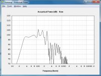
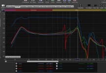
But I'm keen to get other opinions. If you look at Danley's site, literally everything is usable output. For example, let's assume the XOC TH18 is close enough to the Danley TH118 to compare.
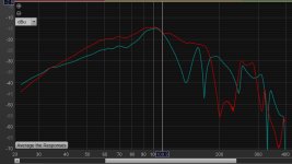
Attachment 1 shows the Hornresp sim of one of the iterations of the XOC TH18. How much usable range would you say that has?
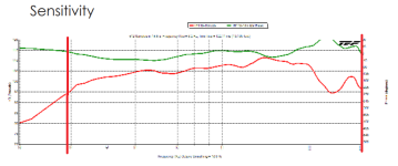
Attachment 2 shows the frequency response of the measured Danley TH118 from their spec page which says "Operating range - 29 - 300 hz -10db, they didn't bother putting a readable graph on the spec page so I added thick red marks to bracket the claimed operating range. Now don't get me started on marketing specs but I don't think the actual listenable operating range is nearly that wide and for that matter -10db is a weird spec when there's a 16 db range between those frequencies. (The spec is based on the -10db down point from their arbitrarily specified 105 db sensitivity, regardless of the fact that there's a 6 db bump above 105 db at other frequencies. The spec sheet is useless, and while I'm complaining, I think the measurement is overly smoothed and that the claimed 1700 watt continuous power rating is bunk, it even says in the owner's manual that "Continuous does not mean "forever"! but then go on to specifically say recommended amp power is 3400 watts. Nothing on the spec page makes any sense and it's meant to confuse people. I hate marketing so much.
This is why |I'm asking questions. People here have heard both the XOC TH18 and Danley TH118 and countless other tapped horns. How much is actually usable? How bad does that group delay actually sound?
Here's my perspective.
Attachment 3 is the Hornresp sim of the ltapped horn I built in early 2009. Looks terrible, right? I can assure you it sounds fantastic with a 24 db low pass at 80 hz. And it doesn't measure like that anyway. Not included in the sim is the extremely light stuffing I added to the horn. Maybe 1 cm thick layer of pink fluffy insulation peeled off a bat and glued to one internal panel for the first few feet.
Attachments 4 and 5 show my measurements. I believe attachment 4 was measured outside, at a distance of 10 meters, with no reflective surfaces like buildings or cars close enough to affect the passband. Attachment 5 I believe is the same thing but just for fun I put a handful of stuffing inside the horn mouth just to see what would happen because the TH SPUD that inspired this horn had mouth side stuffing.
In regular use I do not need the mouth side stuffing, there's no point. The problem harmonics near the passband are completely killed by the throat side stuffing and it isn't used above 80 hz. When I experiment with using it above 80 it sounds fine with music but it makes voices too boomy when watching tv. That might also be a small room acoustics issue that Audyssey can't completely fix but it doesn't matter, there's no need to use it higher than 80.
To comment on your earlier posts, I'm not sure what's going on with the first box you posted, it looks like ia wave cannon type thing. If you have a thread I'm interested to see it.
And the second sub picture you posted appears to be a TH SPUD clone. I'm interested in learning more about that too if you have a link because that sim doesn't look right unless it isn't a TH SPUD clone and/or has really weak drivers in it. It should look like attachment 6, which is the TH SPUD design laid out by TH46 (who was extremely detail oriented) and using the Tang Band W8 740P drivers.
Brian Steele, nice to see you, it's been awhile. I was going to contact you soon with questions about your folding spreadsheets. Anyway, thanks for the tip of using stuffing to approximate box losses. I agree, Ricci chose the compromises that work for him, he prefers huge power density out of tiny boxes. Personally I don't care for that design philosophy at all, it's expensive, and his own measurements show it causes everything to fall apart when compression sets in, starting at relatively low power levels.
Yeah,, I don't know how usable it is, that's why I'm soliciting opinions from people that have tried to use tapped horns in that region. I know Mark Kravchenko always said he didn't like tapped horns and preferred front loaded, but then you need 3x more amp power for the same output.As for trying to smooth out the upper response of the TH by moving the driver further into the mouth, I consider THs as series-tuned 6th order BP designs with poor out of band resonances. The upper impedance peak basically defines the upper useful frequency limit. While you can get the response curve above that point to look a bit better, whether it's actually usable is another matter.
Regardless I love my little tapped horn, I'm hoping to do another instead of a front loaded horn due to the reduced power requirements, if I do another tapped horn I'm going to try to keep the problem resonances at the edge of the passband (no lower than 80 hz), and I'm fully committed to using a bit of stuffing if sounds like group delay or ringing is an issue.
Still looking for opinions from people that use tapped horns in the spiky upper region.
Still looking for an answer to how Audyssey handles big dips in reponse.
Still looking for opinions of whether the added group delay by moving a driver further back from the mouth is worth the trade off of filling in the first big problem hole in response right before the first big problem peak. After reviewing a lot of TH SPUD and DTS 10 information, I think Danley thinks the trade off is worth it, he has no problem moving the back side tap way inside far from the mouth. I just don't have many reviews from people that use those subs in that high frequency range where the resonances are. Danley says they are fine every time someone brings it up in the forums but he's kind of financially obligated to say that.
Attachments
Last edited:
I think your thread title "Tapped horn back tap to mouth distance" gets at the major issue of any TH used at relatively high frequencies.The problem harmonics near the passband are completely killed by the throat side stuffing and it isn't used above 80 hz. When I experiment with using it above 80 it sounds fine with music but it makes voices too boomy when watching tv.
A TH low corner frequency is ~1/4 wavelength, so we hear front and rear path output pretty much as one at the lower end.
The tap to mouth distance for a 40Hz Fb TH is around 7 feet. That's one entire wavelength of 160Hz, in effect the longer rear path an "echo" of the driver's front path at that frequency or higher.
We can EQ response of a reasonably flat TH, but we can't get rid of the echo, the "boom".
The lower the TH goes, the longer the path length, and the lower the unacceptable (to those sensitive to the dual arrival time issue) frequency.
Sealed, bass reflex, and front loaded horns don't have that upper dual arrival time issue.
Art
I just noticed that the attachments in my previous posts are not showing in the order that I uploaded them. This could make trying to follow my narrative and referencing the correct picture very confusing. Fortunately all the pictures are named so it should be possible to figure out what image I'm referring to.
This, and the ability to post pictures inline in the post are the reason I always used to use free image hosting websites instead of attaching images to the forum. Unfortunately all the pictures in all my old threads are gone now.
I will continue to post attachments but I guess from now on I'm going to refer to them by name instead of attachment number.
The tap to mouth distance for a 40Hz Fb TH is around 7 feet. That's one entire wavelength of 160Hz, in effect the longer rear path an "echo" of the driver's front path at that frequency or higher.
Thanks for your reply. Quick anecdote - Back around 2009 when I built my own tapped horn I had a local friend that was also doing some experimenting with a variety of different sub types. He didn't really know what he was doing, he didn't really like asking for advice, he didn't like even mentioning he was working on something until it was built. He showed up at my house one day with a tapped horn in his trunk hooked up to his car stereo. We only listened for a couple of minutes. It sounded like the bass was half a beat behind the rest of the music. It was the strangest thing I ever heard. I never did get any info on the design, the driver, the crossover frequency or slope (but I assume it was his regular 80 hz low pass). I never saw that thing again and he never mentioned it again. I think he burned it. It wasn't what we expected after hearing the one I built. I never got to find out what was wrong with that thing and I should have insisted to analyze it. I'm not sure I'm willing to blame it on the higher harmonics, it couldn't have been tuned low enough to have them anywhere near the passband. But his likely had zero stuffing, so maybe it was harmonics.
Yeah, that's why I was asking for opinions in the first post about group delay issues. Even at the low knee tapped horns have pretty bad group delay unless they are overdamped and weak at tuning.We can EQ response of a reasonably flat TH, but we can't get rid of the echo, the "boom".
When I tried mine with a 120 hz and 100 hz crossover, it sounded fine with music, powerful, as I mentioned. But with tv the voices were also too powerful. Maybe I shouldn't have said boomy. I'm not sure if the issue was something that Audyssey didn't correct properly or if the mains just do a better job with voices than a subwoofer. (Mains are currently Klipsch Heresy which is a 12 inch in a sealed box.)We can EQ response of a reasonably flat TH, but we can't get rid of the echo, the "boom".
The lower the TH goes, the longer the path length, and the lower the unacceptable (to those sensitive to the dual arrival time issue) frequency.
Everyone that has replied here has confirmed my suspicion that I'm probably not going to like the upper range of a tapped horn, even though Danley swears it's fine and his spec sheets call the response up to 300 hz "Operating range".
If I can't keep the spikes far out of the passband I'm going to have to consider a front loaded horn instead, but that comes with it's own issues. For a given volume and low knee it's not quite as strong at the low knee and it's going to suck up 3x more power and exhibit power compression issues as a result.
If I do a tapped horn and keep it around 25 hz I should be able to keep the garbage out of the passband. Basically a scaled up version of my 2009 tapped horn but necessarily more damped to keep size reasonable.
Last edited:
You can fill the dips with some clever folding. Each straight section in the horn path will create mini resonators working for you to fill the dips. They do need to have the right length to match the dip frequency.
Have a look at this example on how to fill dips between peaks in a straight pipe. It is only for understanding.
http://www.hififorum.nu/forum/topic.asp?TOPIC_ID=75743&whichpage=2
Page 2-6 is the most important.
Have a look at this example on how to fill dips between peaks in a straight pipe. It is only for understanding.
http://www.hififorum.nu/forum/topic.asp?TOPIC_ID=75743&whichpage=2
Page 2-6 is the most important.
You can post pictures in line, using the "Insert Image" button:This, and the ability to post pictures inline in the post
This also allows you to resize and align the image if required
Just use a bucket from Home Depot 😂. Sorry, I’m just messing around with a bunch of pipes and junk at the mouth end of a ‘tapped’ qw sub.
It sure is interesting to look at the group delay and ‘echo’ like stuff in the measurement verses what my ears/brain are trying to interpret
I don’t think there’s enough vent air moving (it’s also ‘out of phase with the driver motion) at those frequencies to actually fill that in (with resonance) or fix it enough to be worth your efforts?
Attachments
Last edited:
Jag, I definitely hear what you’re saying when the music changes to a commercial or a podcast or something? All of the funny stuff is so much worse in those, its strange
Maybe I need to a a much larger lower tuned version of the TH18. (That doesn't already exist by the way, does it? I haven't been around for awhile. I need 25 hz or lower tuning.)
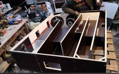
that's the monsters right there
the chair was used as size reference


the chair was used as size reference
Thanks, internal reflections was on the back of my mind, since I was considering a single fold build.You can fill the dips with some clever folding. Each straight section in the horn path will create mini resonators working for you to fill the dips. They do need to have the right length to match the dip frequency.
Have a look at this example on how to fill dips between peaks in a straight pipe. It is only for understanding.
http://www.hififorum.nu/forum/topic.asp?TOPIC_ID=75743&whichpage=2
Page 2-6 is the most important.
Your link is interesting but I am not even close to accepting the fact that folding is the cause of the changing frequency response in those builds. I only got to page 4, I will revisit when I get more time.
The ONLY thing that can cause change due to a fold is reflections. (Let's forget path length if it's folded incorrectly, added air volume in the corners and we'll assume the building material is infinitely rigid).
All I have is theory right now, so correct me if I'm wrong.
Anything within a 1/4 wavelength is close enough to sum.
Anything at a 1/2 wavelength is at the right distance to cancel.
Anything that is a full wavelength apart will sum but be time delayed by the time period of the wavelength.
Looking at the link, the measurements of the folded design had a devasting effect on the lowest two impedance peaks, the lowest one in particular. When you look at the wavelengths of the frequency at the low knee there's no dimension in the folded design that could come anywhere close to touching those lower impedance peaks.
When I have time later I will look into the bump at 55 hz in the single fold design, but I don't think that has anything to do with the fold either. If it did you would see similar bumps at some frequency in the double fold design, but even more exaggerated because there's more reflective surfaces.
At a first glance it looks like these discrepancies (especially the differences in the lowest impedance peaks) are more likely to be cause by something like leaky construction or a less than perfectly sealed junction between the two parts of the box, the separate driver chamber box and the different pipes he clamped it to.
Most pop music has vocals high passed at 18 or 24dB per octave often as high as 160Hz.When I tried mine with a 120 hz and 100 hz crossover, it sounded fine with music, powerful, as I mentioned. But with tv the voices were also too powerful.
Even if the subs are dialed in for music with a +10dB low frequency "haystack", the vocals seldom "boom".
TV is all over the place, lav mics boosting chest resonance, inconsistent HP, etc.
With a low tuned TH, that boosted 120Hz range will sound more overblown than with front loaded cabinets.
"Operating range" does not describe sound, and Danley gives an option between bass reflex, FLH, and TH.Everyone that has replied here has confirmed my suspicion that I'm probably not going to like the upper range of a tapped horn, even though Danley swears it's fine and his spec sheets call the response up to 300 hz "Operating range".
None of DSL's home/ studio line uses TH, which tells the sound quality vs quantity story, "fine", vs "better".
DSL's addition of FLH to the subwoofer line was a response to market demand.
If you are planning for a big horn cabinet, the power difference between a TH and FLH are not much for similar bandwidth range, though one can't expect much beyond 2 octaves for a TH, while a FLH can be decent for near a decade of bandwidth.If I can't keep the spikes far out of the passband I'm going to have to consider a front loaded horn instead, but that comes with it's own issues. For a given volume and low knee it's not quite as strong at the low knee and it's going to suck up 3x more power and exhibit power compression issues as a result.
DSL's measurements of two similar size cabinets, the BC218 FLH (offering two different orientations and frequency /polar response) and the TH812 TH demonstrate how similar they can be. The 8x12" obviously would have a thermal and Sd advantage over the 2x18".
If the TH were using 2x18", the FLH would be neck and neck in the low range, but well ahead in the range above 50Hz both in level and clarity.
The FLH impedance minima is ~32, the TH ~28.
Anyway, for big low tuned cabinets, I'd definitely choose FLH over TH if using a crossover as high as 120Hz.
As the size goes down, the FLH's low end vs top end becomes a music dependent choice.
Art
Thanks. I'm never going to use a 120 hz crossover. (Never say never I guess but I can't think of any reason I would ever need to.) I think about 80 is about as high as I would ever need to go, and back in the day (and sometimes even now) I will go as low as 40 hz so I can boost the lower bass (by an incredible amount) while maintaining ~ equal levels between the sub and the mains up around 80 hz. This gives the car audio boom effect in a living room and sounds great with certain types of music. Mostly though I just let Audyssey give me flat response at the listening position as I'm watching more tv than listening to music these days. And flat response sounds pretty good with rock music type stuff.
The goal here for this project is as much output at the low knee as possible with the least amount of power in a box of reasonable size (let's say 500 liters or so but that's negotiable). It won't be used without a 24 db/oct low pass at no higher than 80 hz. I already have a tapped horn with a low knee close to 25 hz that fits these requirements fine and sounds great, but it uses a 6.5 inch driver, the new project will use an 18. So I already know a tapped horn can do it. I'm just being picky about details.
As for power requirements of a tapped horn and a flh I will show a sim of a comparison with the same driver, same low knee and same overall volume. I haven't done this lately so it will be fun. Maybe later today or tomorrow. I know a sim isn't going to show everything but it will be more than enough to show major differences. And it will show some things that measurements won't.
About this in particular, I'm not trying to draw this out or argue, but the SPUD is aimed at home theaters in particular. In fact there's no other practical use for it at all. The spec sheet even mentions home theater, it's actually the very first thing the spec sheet says."Operating range" does not describe sound, and Danley gives an option between bass reflex, FLH, and TH.
None of DSL's home/ studio line uses TH, which tells the sound quality vs quantity story, "fine", vs "better".
DSL's addition of FLH to the subwoofer line was a response to market demand.
It also says the operating range is 19 to 125 hz. Which includes all the ragged top end stuff, and for that matter, 125 hz is actually way beyond the end of the frequency response graph they show. What it does not say anywhere is that it might sound better if you don't use it above 60 hz, or that a completely different type of sub might be a better choice if you intend to use it from 19 - 125 hz. Even with the (probably) typical 24 db/oct lowpass at 80 hz, the SPUD's first big problem spike is firmly inside the passband.
Danley himself has defended the quality of the ragged top end of tapped horns in person on forums countless times. I've never once seen him suggest that there's anything at all wrong with it. If you know of even once where he's even hinted it's less than perfectly fine please show a link. He's said tapped horn have 3 octaves of usable range countless times.
Danley is undoubtedly more reputable than others in the industry but marketing exaggerations also seem to creep in to some extent, and in this case it's as much what you don't say as what you do. Nobody in their right mind is going to expect this to be usable in any sense up to 125 hz. Except the people who don't know better, and they are going to take whatever the spec sheet says literally.
Attachments
- Home
- Loudspeakers
- Subwoofers
- Tapped horn back tap to mouth distance