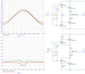
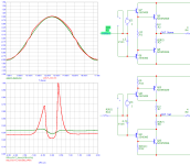
Only the output stage experiences 100:1 current swings. The current swing in the driver stage should be small enough that Hfe remains constant. The pre-driver stage should run at nearly constant current.anatech said:That current gain is highly variable with current.
Ed
Yes, in a perfect world. But we do see other effects that reach back, some through magnetic fields or power supply fluctuations. Sometimes those smaller current variations do matter in the Vas.
Mosfets have been used in the past to isolate current variations in the predriver stage as well. Many directions to reduce the effects of dynamic loading.
Mosfets have been used in the past to isolate current variations in the predriver stage as well. Many directions to reduce the effects of dynamic loading.
Mine has separate boosted regulated supplies for the voltage amplifier stages, two high current supplies for the output stage. The power transformer is practically dead center on a sub chassis. It's even an E-I type (shielded)! Each has it's own winding, including housekeeping and lamps.
So many details go into a great amplifier.
So many details go into a great amplifier.
I am reminded of the old saying that something isn't rocket science. Amplifier design is rocket science.
Ed
Ed
It kind of is. So many things to take into account. You make your best compromises.
And non-linear as hell.That current gain is highly variable with current.
Jan
Which is why when you limit yourself to two stages of current gain, and use up every uA available from the VAS, you choose the most linear output and driver transistors you can get your hands on.
I use Mosfets for all my AB amplifiers and the 2 tests are : Unity gain stable and good sound quality using NO bias on the IRF240 /9240 outputs. That is 0v (gates shorted) .
On the scope it looks bad > 15khz.
There is slight raspy distortion in the top end but otherwise good.
At 6.7v bias distortion is 0.003%
On the scope it looks bad > 15khz.
There is slight raspy distortion in the top end but otherwise good.
At 6.7v bias distortion is 0.003%
I am reminded of the old saying that something isn't rocket science. Amplifier design is rocket science.
Ed
Seems to me the whole Vbe thing has been turned from a molehill into a mountain, and I blame Self for that 😉. I use a SOT23 sensor right next to one of the power transistor's collector legs and have great success with this. You’ll notice a small area of copper near the SOT23 collector. I call this a ‘thermal paddle’ and it improves the coupling to the power transistor collector leg. You can put a small dollop of thermal grease over the paddle to the collector lead, but I found most times you do not need it.
It’s very fast because the SOT23 thermal sensor trannie thermal mass is low.

(I worked in industrial electronics for about 7 years and learnt a trick or two about temperature sensing)
It’s very fast because the SOT23 thermal sensor trannie thermal mass is low.
(I worked in industrial electronics for about 7 years and learnt a trick or two about temperature sensing)
Last edited:
Center of pressure , Center of balance, make the fins too big.It kind of is. So many things to take into account. You make your best compromises.
I think I found rockets more simple as a kid. LOL
But true always compromises. It does actually get rather complicated.
Of course, colleague, but let's check.Not at all. You can't isolate an output stage from the circuit that drives it.
Simple basics, CFP vs Darlington.

Not bad, sure output impedance in CFP are lower due to intrinsic feedback and stage provides really lower total error from input to output.
But in real world such a stage oftenly used as output and being driven from VAS.
VAS usually have high output impedance and so (but really excuse me) in our model we can just increase input impedance to say 680 Ohm.
Sic!, not 47k as usually you can see at the VAS output!

Darlington keeps his known and smooth output error vs output current.
But CFP... CFP provides you with a complex high-bandwith errors which are too complicated to create something useful with it.
Yes, but millions of flies flocking to **** also can't be wrong. This is sad.Products exist
Last edited:
Hi BesPav,
Firstly, I haven't seen any good amplifiers driving an output stage like a CFP without more current gain (slightly different output configuration) or buffered Vas. You can pick on a poor example to prove a point, but what have you shown but a poor design practice?
Totally agree with you about people making poor products popular. Advertising and the power of suggestion. Yes, they are often wrong and this explains so much in life. Sheeple.
Hi Bonsai,
Excellent idea. Thanks.
Another way is to place signal diodes on either side of the collector lead(s), perpendicular to the lead pattern on the PCB. Again, low thermal inertia and good coupling. Seems to work pretty well.
Excellent idea. Thanks.
Another way is to place signal diodes on either side of the collector lead(s), perpendicular to the lead pattern on the PCB. Again, low thermal inertia and good coupling. Seems to work pretty well.
What bias do you run at with EF2 and CFP.Darlington keeps his known and smooth output error vs output current.
But CFP... CFP provides you with a complex high-bandwith errors which are too complicated to create something useful with it.
With the optimal bias, the performance of them is about the same.
Yes, in my simulation, there are optimal bias points. I know someone would argue simulation is not the reality. Anyway, my point is CFP perform just as good as EF2. The benefit of CFP is that it runs significantly cooler (lower bias).
Both run at 10KHz. The output is about 10Vp.
The EF2 is biased at 102mA
The CFP is biased at 7mA
Hmmm...Firstly, I haven't seen any good amplifiers driving an output stage like a CFP without more current gain
Say Cavalli-Can Kumisa III
https://www.amb.org/audio/ck2/
But, it is in A-class and because of this performs very well.
I'm not sure. I think at higher power levels and lower impedance speakers it may have problems. You still have the load impedance variation reflected into the Vas.
An improved version would have more current gain in the output stage, or a buffered Vas. The result is similar either way.
An improved version would have more current gain in the output stage, or a buffered Vas. The result is similar either way.
In my case bias is not an issue.What bias do you run at with EF2 and CFP.
Main problem is broking intrinsic in-stage feedback twice the swing.
This creates so much problems that resolving them are a way harder than just using well-designed Darlington.
By the way.
Bias is not a main thing in EF stages.
Maybe we need here at DIYAudio a dedicated thread about optimizing and stabilizing EF3 stage like this one?
https://forum-vegalab-ru.translate.goog/showthread.php?t=92336&page=2&p=3049608&viewfull=1&_x_tr_sl=ru&_x_tr_tl=en&_x_tr_hl=ru&_x_tr_pto=wapp#post3049608
- Home
- Amplifiers
- Solid State
- Optimal bias in push-pull EF output stage: textbooks and reality