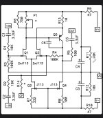
Q3 and Q4 work as CCSs so you can keep them as J113 as I don't think putting 2SK170 in those positions would make much difference in sound. The value of R7 and R8 would not need to be changed if Q3 and Q4 are not changed.
If you wish to change Q3 and Q4, then choose resistor values for about 3mA and 9mA:
If you wish to change Q3 and Q4, then choose resistor values for about 3mA and 9mA:
A little under 3 ma and 9 ma. Approximate, but not at all critical.

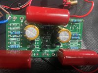
What are the voltages across resistors R7, R8, R9, R11, and R12? Also across R6?
Is 24VDC present on the FE board at V+?
Is 24VDC present on the FE board at V+?
Last edited:
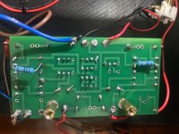
In your first picture, I think you should reflow the solder joint for the red wire to IN+.
Check the value of R9.
The colour code appears to be yellow violet black red brown. That translates to 47k, not 47R as required.

The colour code appears to be yellow violet black red brown. That translates to 47k, not 47R as required.
Ben Mah - the best audio proofreader!
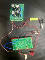
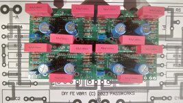
A follow up with the FE2022 (using 2sk170s) driving a BA2 complementary output state. Sound staging (especially driving it differentially) is quite good.
Distortion measurements yet to come.
BA2 output stage running at 15W per MOSfet (~28V volt rails).

Distortion measurements yet to come.
BA2 output stage running at 15W per MOSfet (~28V volt rails).
Check the value of R9.
The colour code appears to be yellow violet black red brown. That translates to 47k, not 47R as required.
View attachment 1468014
Thanks you very much Ben, It is now singing well. good bias voltages now to the fets. It was a simple mistake I made. Maybe I’m getting old and too confident.hehe This will be my 2nd preamp (after acp+). Anyway thank you.cheers
- Home
- Amplifiers
- Pass Labs
- DIY Front End 2022