Hi, I need dual rails or a negative rail in addition to the single + 12v to power some op-amps based filters ( band pass for LED Spectrum analyzer ).
Power consumption I assume will be low.
I would like to use a " brick wall adapter " that outputs only a single rail ( 12 or 14.4V at a few amps ).
I found this setup with 7812 / 7912 , anyone used this ?
Thank you,
- Bruno.
EDIT:
I miss read the ic, seems to be " R-78CKxx-05 " can a 7912 be used there ?.
Attachments

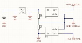
I miss read the ic, seems to be " R-78CKxx-05 " can a 7912 be used there ?.
Definitely not.
What you want is a small DC/DC converter that gives +12, -12 from a 9 to 15 volt input.
Like these. The search function shows 1000's of different types so you will have to find one. I've tried and given up 🙂 These work well and are easy to use.
https://uk.farnell.com/c/power-supplies/dc-dc-converters/isolated-through-hole-dc-dc-converters
The output of these is fully floating so no ground issues.

Here:
https://www.murata.com/products/productdata/8807031275550/kdc-nmk.pdf
https://uk.farnell.com/murata-power-solutions/nmk0515sc/converter-dc-dc-sil-2w-15v/dp/1673894
You want a 12 volt version. Look at the data sheet for the numbers.
https://www.murata.com/products/productdata/8807031275550/kdc-nmk.pdf
https://uk.farnell.com/murata-power-solutions/nmk0515sc/converter-dc-dc-sil-2w-15v/dp/1673894
You want a 12 volt version. Look at the data sheet for the numbers.
I think that would be the way to go, and they are cheap.What you want is a small DC/DC converter that gives +12, -12 from a 9 to 15 volt input.
Thank you.
They are good, I've used them for various things in the past.
Make sue you get the voltages and current ratings you want. There are so many to choose from that searching the sites for what you want is difficult but they are cheap and readily available from lots of places.
All they need to work well are small caps at the input and across each rail fitted close to the converter. Do not fit large caps across the output rails, they don't need them and they can stop it working properly. 10uF is a typical value, don't fit bigger, it doesn't them and they will cause problems if you do.
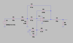
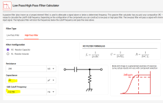
Using this calculator. for the filters, haven't picked values yet.C5 looks big in relation to working into 200k (0.08Hz -3db
Even 0.1uF works. maybe 1uF for all input caps caps . or use smaller value for higher frequencies.
There will be 10bands.
- So , using a single rail supply is fine. will +-6V be enough to output 2.5V ? ( 2.5v for max amplitude , last LED. to LM3914 ). I can't find output voltage swing vs supply voltage for NE5532, 4558 seems to output +-4V at +-5V supply , seems a bit optimistic tho.
+-6V , even 2v per rail loss, it's +-4V so around 2.8Vrms ?
Attachments
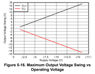
12 volts (doesn't matter if it is 12v single rail or -/+6v split rail) for the opamp will get you your 2.8 volts rms you mention. If you try going a bit lower on rail voltage then the choice of opamp becomes more critical.
The 5532 is fine but is also quite a high current consumer which you don't want if using a DC/DC converter.
The 5532 is fine but is also quite a high current consumer which you don't want if using a DC/DC converter.
Nevermind, simpler to get a high current op amp
NJM4556A
JRC4556A 70mA might do it.
Or something better.
NJM4556A
JRC4556A 70mA might do it.
Or something better.
The 4556 is often used for headphone use. Its a good chip.
Working just from pictures is difficult 🙂
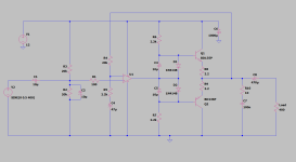
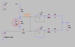
Looks like you are using one half of the opamp. Why not run in parallel to get more current.
It's the grounding ok ?. Maybe a resistor in series with the diodes, or a Vbe multip instead.
Working just from pictures is difficult 🙂
Looks like you are using one half of the opamp. Why not run in parallel to get more current.
Forgot the schematic ...Working just from pictures is difficult
Attachments
I never did run op amps in parallel. but I've seen the approach on the forum.Looks like you are using one half of the opamp. Why not run in parallel to get more current.
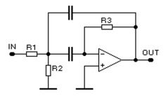
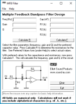
I need a buffer ( with gain ) that runs the 10 MFB band pass filters, I'm assuming one simple op amp might struggle.
Or use a buffer unity gain , and make the filters with gain ? like 5 or 10 instead of 1 ?.
That circuit should be fine from one opamp. The simulation will show the sort of opamp output currents involved... they should be quite low.
400 ohm as a load is high enough to drive from a parallel opamp setup with the right opamp. That would simplify the circuit to essential a few components. This would translate to a single rail design easily enough. Shown as unity gain but can be made to have gain in the usual way.

400 ohm as a load is high enough to drive from a parallel opamp setup with the right opamp. That would simplify the circuit to essential a few components. This would translate to a single rail design easily enough. Shown as unity gain but can be made to have gain in the usual way.
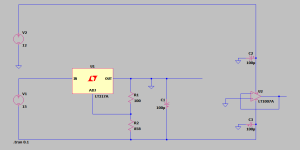
I'm not sure if I need two voltage dividers, on per amp , or one like this will do :400 ohm as a load is high enough to drive from a parallel opamp setup with the right opamp. That would simplify the circuit to essential a few components. This would translate to a single rail design easily enough. Shown as unity gain but can be made to have gain in the usual way.
and the output caps before or after R10 / R11.
Attachments
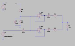
One divider is fine though. Just spotted a mistake in your diagrams. You have decoupled the divider to ground with a cap which will short the signal. Use a resistor from the divider to the opamp.
R2 ?One divider is fine though. Just spotted a mistake in your diagrams. You have decoupled the divider to ground with a cap which will short the signal. Use a resistor from the divider to the opamp.
Attachments
- Home
- Design & Build
- Electronic Design
- PSU Help!