I picked up an old Bose LSPS subwoofer module with a blown amplifier from my uncle yesterday. My idea was to remove the blown amplifier and convert it into a simple subwoofer for my daughter to use in her car. It looks like a simple two-driver vented box, but when I removed one of the drivers and the amplifier, the internals weren't just chamber and a vent like I expected. Instead, it looks like each driver is mounted in folded tube that terminates in a vent.
Anyone know what's going on inside one of these things? I was first thinking it's probably an offset-driver TL alignment, but one of the drivers is located near the end of the folded tube, and the tube looks like it has to traverse the length of the box at least twice before it meets the other driver. I've searched online but haven't turned up anything yet.
Another thing - the drivers seem to be wired in parallel and present a combined impedance that drops as low as 1.3 ohms (measured using my DATS). The curve looks like the classic double-peak of a vented alignment, but the lower peak is HEAVILY damped. The dip between the two peaks doesn't appear to be that damped though, which is what I would have expected if the heavy damping of the lower peak was caused by a fully-stuffed enclosure.
Later on today I'm going to take it apart a bit further to see if I can figure out what's going on inside it. One driver is easy to remove. The other, not so much ...

That's the model, yes.
This is what the measured impedance looks like. Note the significantly damped lower peak. Looks like I was incorrect about the dip at Fb at well - it also suggests that there's lots of stuffing in the enclosure. Didn't expect to see that in a Bose bass module.

This is what the measured impedance looks like. Note the significantly damped lower peak. Looks like I was incorrect about the dip at Fb at well - it also suggests that there's lots of stuffing in the enclosure. Didn't expect to see that in a Bose bass module.
It look to me the lower peak is significate smaller in amplitude than higher peak because of the very low 45 Hz vent (de)tuning frequency of the bass module, which is rather low for those 5-inch "subwoofer" drivers used by Bose. Apparently some active equalization is helping here.
You called it - I took the drivers out of the box and measured their t/s parameters (excluding Vas). Average Fs worked out to around 74 Hz with a Qts of around 0.7. Re is pretty low, at ~2.5 ohms per driver.
Hmm... with those specs, those drivers would make pretty decent in-door midbass drivers for a car audio system.

Both driver chambers are lined 50% stuffed along their length with what looks like polyester fiberfill, which I think also explains the lower impedance peak and the impedance at Fb (43 Hz) being noticeably higher than the DC resistance of the drivers in parallel.
The internal layout of the cabinet is pretty interesting. I'm not sure what to make of it. While the drivers are connected in parallel, their loading seems to be quite different at first glance. All of the bends in the enclosure are curved btw, not straight like illustrated below. Any ideas what's going on here? Because the drivers might be loaded differently, the response will likely be different if I wire the drivers up in series as I was planning to do (to get a combined impedance of just over 4 ohms, which is a bit more friendly to most amplifiers than the original 2 ohm impedance between 30 Hz to 120 Hz).

Hmm... with those specs, those drivers would make pretty decent in-door midbass drivers for a car audio system.
Both driver chambers are lined 50% stuffed along their length with what looks like polyester fiberfill, which I think also explains the lower impedance peak and the impedance at Fb (43 Hz) being noticeably higher than the DC resistance of the drivers in parallel.
The internal layout of the cabinet is pretty interesting. I'm not sure what to make of it. While the drivers are connected in parallel, their loading seems to be quite different at first glance. All of the bends in the enclosure are curved btw, not straight like illustrated below. Any ideas what's going on here? Because the drivers might be loaded differently, the response will likely be different if I wire the drivers up in series as I was planning to do (to get a combined impedance of just over 4 ohms, which is a bit more friendly to most amplifiers than the original 2 ohm impedance between 30 Hz to 120 Hz).
Impedance of each driver in the cabinet (other driver replaced with a blank to block its mounting hole) shows that they're loaded a bit differently.

Yup, that's it exactly! What's the patent #? I'd like to have a read of it to understand what it's all about.Kinda looks like this part of the old Bose patent ?
from the image looks more like TML but impedance like a reflex system.
However the damped lower peak means its not very efficient?
However the damped lower peak means its not very efficient?
I can’t seem to find the right one?
https://patents.google.com/patent/EP0489551B1/en
@GM do you have the correct link by chance ?
https://patents.google.com/patent/EP0489551B1/en
@GM do you have the correct link by chance ?
Ah, I found it. It's an interesting read.Yup, that's it exactly! What's the patent #? I'd like to have a read of it to understand what it's all about.
https://patentimages.storage.googleapis.com/af/f5/44/e865921a2c916b/US20020085731A1.pdf
That looks like the patent for their 8th order BP module used for the AM series.
Average Fs worked out to around 74 Hz with a Qts of around 0.7.
As I said, 45 Hz tuning is very low for that high Fs=74 Hz. Because of that, lower peak is damped - nothing unusual here.However the damped lower peak means its not very efficient?
But unusual is the whole double-ofsett-driver-in-a-TL system for eliminating the first dip in TL frequency response. Will be interesting to see measurements how effective this system is.
It looks like they wanted to improve on the advantages of the basic offset-driver transmission line. Unfortunately, I don't think this can be sim'd in Hornresp, as multi-driver sims in Hornresp assume that the drivers are mounted close to each other, and I don't know if that could ever change (unless David introduces an option to put one driver at S2 and the other at S3, hint, hint, LOL). But it does bring up some interesting ideas...
For example, what would be the result if we mount two drivers in an ODTL so that the center point between them is 1/3rd the way down the line (to null out the 1st harmonic resonance), but the drivers are separated by half-wavelength of the next harmonic resonance?
For example, what would be the result if we mount two drivers in an ODTL so that the center point between them is 1/3rd the way down the line (to null out the 1st harmonic resonance), but the drivers are separated by half-wavelength of the next harmonic resonance?
Last edited:
As I said, 45 Hz tuning is very low for that high Fs=74 Hz. Because of that, lower peak is damped - nothing unusual here.
But unusual is the whole double-ofsett-driver-in-a-TL system for eliminating the first dip in TL frequency response. Will be interesting to see measurements how effective this system is.
You called it. The lower peak is lower in level because of the high driver Fs. However, it's also more rounded than expected, and I put that down to the damping used in the chambers behind the drivers, as illustrated in the diagram below. I'm not sure if any damping is used in the vent that's connecting the two chambers.
Example ODTL with similar driver, with different levels of damping.
Oh, the Bose patent mentions the following wrt what I think is the LSPS subwoofer:
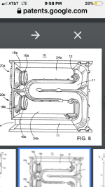
"Referring now to FIG. 8, there is shown a cutaway perspective view of an exemplary electroacoustical Waveguide system according to the invention. The waveguide system of FIG. 8 uses the implementation of FIG. 6, With the FIG. 8 implementation of the elements of FIG. 6 using common identifiers. In the implementation of FIG. 8, Waveguide 11 has a substantially uniform cross sectional area of 12.9 square inches and a length of 25.38 inches. The acoustic volumes 24a and 24b have a volume of 447 cubic inches and 441 cubic inches, respectively, and the acoustic drivers are 5.25 inch 3.8 ohm drivers available commercially from Bose Corporation of Framingham."
The drivers are actually 2.45 Ohms, but the rest seems to be a decent description of the LSPS subwoofer.
The patent does have a few "errors" though, e.g. nulling out the 1st harmonic resonance requires placing the driver closer to 0.33*L, not 0.25*L, but the rest of it does make a decent read, once you can make it through the technicalese ... 🙂.
Also of interest is that this patent that describes basically what is an ODTL as "prior art" was filed over 20(!) years ago.
There is another question to be answered though - why did Bose elect to use drivers with such high Fs (~74 Hz) and high Qts (~0.7) in a bass module that's tuned to around 43 Hz? I have a suspicion that it's to improve power handling at frequencies below Fb...
People like to knock Bose... but they were doing stuff with itsy bitsy drivers and plastic boxes long before Sonos or Samsung or Apple... and they basically had their won Speaker University at MIT, and had PhDs do a truckload of mathematical modelling via software...
That looks like the patent for their 8th order BP module used for the AM series.
8th order bandpass:
8th order BR:
6th order BR:
- Home
- Loudspeakers
- Subwoofers
- Bose LSPS Subwoofer Model (v1)