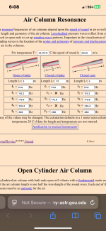
Hornresp Update 5740-250413
Hi Everyone,
CHANGE
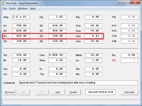
Previously a mass loaded transmission line loudspeaker design template generated using the Input Wizard had four segments, with the third segment being 0.01 cm long to act as the interface between the end of the transmission line and the port tube mass loading (see Attachment 1). The MLTL design template now has three stepped segments (see Attachment 2).
BUG FIX
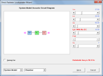
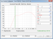
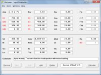
With a bass reflex design if the green fundamental frequency marker was added to the loudspeaker wizard charts (see Attachment 3) and the Schematic or System Model option then selected (see Attachment 4), when the Lpt label was double-clicked to include or remove the end correction the Helmholtz resonance frequency value was not being updated (see Attachment 5). This has now been fixed (see Attachment 6).
Kind regards,
David
Hi Everyone,
CHANGE
Previously a mass loaded transmission line loudspeaker design template generated using the Input Wizard had four segments, with the third segment being 0.01 cm long to act as the interface between the end of the transmission line and the port tube mass loading (see Attachment 1). The MLTL design template now has three stepped segments (see Attachment 2).
BUG FIX
With a bass reflex design if the green fundamental frequency marker was added to the loudspeaker wizard charts (see Attachment 3) and the Schematic or System Model option then selected (see Attachment 4), when the Lpt label was double-clicked to include or remove the end correction the Helmholtz resonance frequency value was not being updated (see Attachment 5). This has now been fixed (see Attachment 6).
Kind regards,
David
Attachments


Last edited:

With a bass reflex design if the green fundamental frequency marker was added to the loudspeaker wizard charts (see Attachment 3) and the Schematic or System Model option then selected (see Attachment 4), when the Lpt label was double-clicked to include or remove the end correction the Helmholtz resonance frequency value was not being updated (see Attachment 5). This has now been fixed (see Attachment 6).
Hello David,
The Sherlock in me saw a color difference related to RP between attachment 4 and 5 (from yellow to blue), this is to provide a visual feedback to the user that RP has changed due to end correction flag. Are there other blocks from System Model that change their colors to indicate flag state? Interesting feature, you are always bringing improvements.
D may change color to indicate semi-inductance flag on.
Horn segment H1, H2, H3, H4, may change color to indicate continuous or stepped.
I'm not remembering all the flags activated by double clicks.
Best regards,
Marcelo
The Sherlock in me
My dear Holmes,
RP and PT change to blue when Lpt has no end correction because the port tube then effectively operates similar to a segment (which is normally also blue).
Segments change from blue to grey when filling material is added, as does the rear chamber (from green) when acoustical lining material is specified.
Lossy Le, Semi-inductance and FDD models are already indicated by check boxes.
Stepped segments are already indicated by the area slider label.
Kind regards,
Dr. Watson 🙂
My poor head. When will I ever catch up. 25 years using this program and I still don't know all the parts 😊
Hornresp Update 5750-250427
Hi Everyone,
CHANGE
The Input Wizard now has a U-Frame open baffle loudspeaker option, and the closed box, passive radiator, bass reflex and transmission line options now have associated explanatory notes.
Kind regards,
David


Hi Everyone,
CHANGE
The Input Wizard now has a U-Frame open baffle loudspeaker option, and the closed box, passive radiator, bass reflex and transmission line options now have associated explanatory notes.
Kind regards,
David
Hornresp Update 5750-250512
Hi Everyone,
BUG FIX
Steps to generate the error:
1. Calculate bass reflex loudspeaker combined acoustical power response
2. Select menu Tools > Output > Direct Radiator
3. Select menu Window > Phase Response
4. Capture current results
5. Select menu Window > Acoustical Power
6. Select menu Tools > Output > Port
7. Select menu Window > Phase Response
8. Select menu Tools > Compare Captured
Form title should read Hornresp - Phase Response not Hornresp - Acoustical Power:

The bug has now been fixed:

Kind regards,
David
Hi Everyone,
BUG FIX
Steps to generate the error:
1. Calculate bass reflex loudspeaker combined acoustical power response
2. Select menu Tools > Output > Direct Radiator
3. Select menu Window > Phase Response
4. Capture current results
5. Select menu Window > Acoustical Power
6. Select menu Tools > Output > Port
7. Select menu Window > Phase Response
8. Select menu Tools > Compare Captured
Form title should read Hornresp - Phase Response not Hornresp - Acoustical Power:
The bug has now been fixed:
Kind regards,
David
Unfortunately the bug is not fully fixed. Another update coming in the next few days.
Hornresp Update 5750-250513
Hi Everyone,
BUG FIX
The last update did not completely fix the problem - form title errors could still occur under some circumstances, as shown in the example below.
Hopefully the bug has now been fully resolved.
Kind regards,
David

Hi Everyone,
BUG FIX
The last update did not completely fix the problem - form title errors could still occur under some circumstances, as shown in the example below.
Hopefully the bug has now been fully resolved.
Kind regards,
David
guys maybe a stupid question but the tutorial of a few years old says you should manually enter driver parameters, I see at Loudspeaker.database you can download a file like for WinISD. I just dont understand how to load it into the Hornresp program. Clicking on help gives an error message and no help page or file. Can someone be so kind and point me to where this is explained? Many thanks in advance.
Did you clikck on help in the menu or the help file itself? Because the help file isn't the standard Windows .hlp format. It is supposed to be opened from the menu in Hornresp.
I haven’t tried importing files from the database (it does have a Hornresp format, use that), but try the File -> Import menu and see if you find something.
I haven’t tried importing files from the database (it does have a Hornresp format, use that), but try the File -> Import menu and see if you find something.
Check is You find the driver on loudspeakerdatabase.com, if You do, a bit down You will find export options for different simulation software.guys maybe a stupid question but the tutorial of a few years old says you should manually enter driver parameters, I see at Loudspeaker.database you can download a file like for WinISD. I just dont understand how to load it into the Hornresp program. Clicking on help gives an error message and no help page or file. Can someone be so kind and point me to where this is explained? Many thanks in advance.
For HornResp - copy the downloaded file to c:/hornresp/drivers
To load this drivers data into HornResp, You first start a new simulation with the "Add" button, then choose "File"-"Paste driver from database". Now You should be good to go 🙂
Grazie! How simple that was. Sometimes you just dont see whats right in front of you.
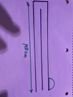
is it two open ends (halfwave for 300cm is 57.6hz) on a pipe that is out of phase with the driver that is postioned at the vent exits?
Exits both red arrows(even though the other vents have been ‘zeroed out in length and crossection)
Attachments
Last edited:
Turd in the punchbowl!
Now I described it as a long chamber (instead of the ‘port’ section) and it’s no longer out of phase ? Or using halfwave (double open ended)?
Last edited:
is it two open ends (halfwave for 300cm is 57.6hz) on a pipe that is out of phase with the driver that is postioned at the vent exits?
Not sure what you are trying to do, but for the given input values you have in effect specified three cylinders, each having a cross-sectional area of 200 cm^2 connected as shown below (check against the system model).
Exits both red arrows(even though the other vents have been ‘zeroed out in length and crossection)
As far as I can see, your port cross-sectional areas have not been 'zeroed out'.
Now I described it as a long chamber (instead of the ‘port’ section) and it’s no longer out of phase ? Or using halfwave (double open ended)?
Still not sure what you are trying to do 🤔.
Last edited:
I thought maybe it was describing this affectively, but I can’t wrap my head around the descriptions and schematic as easily as I can in the other sections (Nd,Od,th, ph, etc)
As if it was a double open ended pipe (with no box or chambers involved)

As if it was a double open ended pipe (with no box or chambers involved)
Last edited:
A sidenote ; maybe You are familiar with the works of Thomas Lato and others on dampening resonances? Something called an infinity tube (or a spin-off) might be usefulTurd in the punchbowl!
- Home
- Loudspeakers
- Subwoofers
- Hornresp