I won a box of Type 85 triode tubes at an auction and wanted to use them in a new build and already had a stash of E80L
 . It is inspired by the Zen Triode by Decware. The E80L is similar to the Russian 6P15P-EV that they use, only more linear. I am Very happy with the sound of this simple, basic amp. The 85 is a fine low mu triode. I am so happy I bought those.
Attachments

Nice looking amplifier.
From the schematic I see that g3 of E80L is floating. It should be connected to ground or to plate.
When connected to plate you get a bit higher gm and lower rp.
Maybe a bit more power too.
There is also mentioned in the schematic, that cathode circuit of two E80L tubes are shared.
That is a bad desing flaw.
Separate cathode resistors (and capacitors) should always be used.
Thanks for looking. The g3 pin is tied to the cathode by a .1uF cap. Also, if you look up the Decware schematic, he ties the cathodes. I thought, like you, that they should be separate, but he explains the rational in his video about the amp. It tends to balance the tubes. I looked into it and found that it is done sometimes. Hey, I had a bunch of tubes and hardware and thought I'd try out his design scheme to see how it performed. Check out his video here:
On the Decware website you can go to this amp and scroll down to the schematic. Here's a screen grab.

Artosalo, I took some time to think about your comments. Do you realize that you, 1-didn't ask why I used the schematic that I chose, 2-you assumed that I don't know what I'm doing and 3-you told Steve Deckert that he sucks as a amplifier designer. You also made blanket statements about one of the most talked about amps on the internet. The guy has something like a 2 year waiting list. My hobby is designing amplifiers from scratch and building them. This was the first time in several years that I've tried someone elses design just to see how it sounded. Of course I did it with different tubes, because I wanted to. Now anyone who looks at my post is going to see your comments and think it's a bad design because you didn't think that you might be able to learn something new along the way. I guess you're the world authority on tube amplifier design.Nice looking amplifier.
From the schematic I see that g3 of E80L is floating. It should be connected to ground or to plate.
When connected to plate you get a bit higher gm and lower rp.
Maybe a bit more power too.
There is also mentioned in the schematic, that cathode circuit of two E80L tubes are shared.
That is a bad desing flaw.
Separate cathode resistors (and capacitors) should always be used.
This is a very good sounding amplifier. It uses tubes that not many people are used to seeing. It proves that what you called a bad design flaw is actually something that works quite well.
Way to go.
There was a lot of discussion previously on this schematic: Some quick questions on Zen Decware EL84 SET schematic
I didn't read it all, but does divide the audience.
The 85 (~= 55, 6V7G) has a gain around a quarter of a 6N1P at around 8. What source do you use? I saw the loadline was referencing 5.5V?
I am also a fan of giving a new lease of life to these old wonderful tubes, so will follow the discussions here with a lot of interest!
I'm using an Eversolo DMP A8 as a source. It has a 2.5 volt output preamplifier built in. If you look at the E80L tube load line, my operating point is at -8 grid volts. So with this design a gain stage with mu of 8 is fine. I still can't turn the preamplifier up all the way. My Zu Audio DWX speakers are 90 something dB sensitive. I've found that those old, low mu tubes work great with output tubes that max out around -20 grid volts. The reason I have a bunch of E80L tubes is the previous O1a - E80L mu follower amp I posted. I love that thing! I can only turn it up half way.
Well, that was the point. I saw what he did and thought maybe I could learn something from him, so I built my version of his circuit. I said it sounds and performs great. Really good results do not equal a very bad design. I learnd something and thought I'd share. That's all.There was a lot of discussion previously on this schematic: Some quick questions on Zen Decware EL84 SET schematic
I didn't read it all, but does divide the audience.
The 85/55/6v7G is another old design with a cylindrical anode (like the 2A5/42/6F6) that some prefer. Nice to see it getting an outing in a new build 🙂I am also a fan of giving a new lease of life to these old wonderful tubes, so will follow the discussions here with a lot of interest!
Since my purpose was to understand and evaluate the circuit, I had a little discussion with ChatGPT about the shared cathode resistor discussion. I may owe Artosalo an apology. please have a read of the AI opinion.
Shared Cathode Resistor in Stereo SET Design — Technical Evaluation
In a recent amplifier build, I used a shared, fully bypassed cathode resistor for the two output tubes in a stereo single-ended triode (SET) amplifier — one output tube for the left channel and one for the right. This design choice received criticism from other builders, so I took a deeper dive into the technical implications. Here's a summary of what I found.
How Vacuum Tubes Work — A Quick Refresher
Electrons are emitted by the heated cathode and flow to the plate (anode), where they are collected.
The grid modulates this current by controlling the electron flow — more negative grid = less current.
The voltage between the grid and cathode (Vgk) is critical. If the cathode voltage changes, so does the tube’s effective bias.
What Happens When Cathodes Are Shared?
By tying both output tube cathodes together and using a single shared cathode resistor (bypassed with a capacitor), the two tubes:
Share the same DC bias point
Share the same AC signal ground reference at the cathode
This means any change in current from one tube will affect the cathode voltage seen by the other.
---
Key Technical Consequences
1. AC Crosstalk Between Channels
Since each tube is amplifying a different channel (left vs. right), the signal-induced current from one tube flows through the shared cathode circuit. This modulates the shared cathode voltage, which alters the bias of the other tube in real-time.
This results in intermodulation distortion and channel crosstalk
Stereo separation is compromised
The amplifier develops a kind of "cross-linked" sonic character that's not true to the input signals
2. Bypassed Resistor Does Not Prevent Interaction
Even though the cathode resistor is fully bypassed, the bypass capacitor is not a perfect short — especially at low frequencies. The shared AC impedance at the cathode allows signals to influence each other, albeit slightly rolled off at higher frequencies. The effect is most audible in the midbass and low midrange.
3. The Designer’s Rationale — Self-Balancing Bias
The original justification was that this configuration provides automatic bias balancing: if one tube pulls more current, the shared cathode voltage rises, slightly rebiasing both tubes in a way that brings them back into balance.
This effect does exist, but it only applies to the DC operating point, not to signal-level operation. Moreover, this self-balancing mechanism is more useful in:
Mono amps with paralleled output tubes
Push-pull amps with shared cathodes
Situations where the tubes handle the same signal
It does not apply when the tubes are amplifying two different signals, as in a stereo amplifier. In fact, the shared cathode in a stereo design defeats proper channel isolation.
---
Conclusion
Using a shared, bypassed cathode resistor for the left and right output tubes in a stereo SET amplifier is technically unsound. While it may provide some minor DC bias equalization, it introduces:
Undesired AC signal interaction
Crosstalk between stereo channels
Loss of stereo separation
Potential for unpredictable distortion as the channels modulate each other's operating points
This is not just unconventional — it's a real design flaw when stereo fidelity is the goal.
---
Recommended Fix
Each output tube should have its own cathode resistor, and ideally its own bypass capacitor. This ensures:
True channel independence
Stable bias for each tube
No inter-channel modulation
If desired, bias current matching can be handled with separate bias resistors, adjustable fixed bias, or matched tubes — without compromising signal integrity.
That is a little concerning that Chat GPT has more credence than a highly respected contributor.
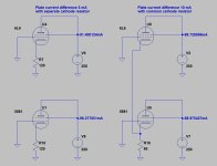
Here is an simulated example of the effect of common cathode resistor vs. separate resistors to plate current of each tube.
The simulation is made with 6L6 and 5881 tubes, since these are very similar but still there is a small difference, which is required for the simulation.
The simulation is made with 6L6 and 5881 tubes, since these are very similar but still there is a small difference, which is required for the simulation.
Attachments
In the video linked to in post #3 the reason for the shared cathode resistor is given from 12:35 going. Stated is that the shared cathode resistor tends to balance the two tubes current wise. But no explanation of why this would be so is given in the video.
The following is a passage from pages 47 and 49 of the book "Hi-Fi Amplifier Circuits" by E. Rodenhuis (Philips, 1965) about the advantage of using seperate cathode resistors for the two power tubes (EL84's) in a push-pull output stage.

So, according to this passage the opposite of what is stated in the video is true. Separate cathode resistors compensate for differences in characterisitics of the tubes d.c. current wise.
This supports what artosalo already put forward.
A link to the complete book: Hi-Fi Amplifier Circuits
The following is a passage from pages 47 and 49 of the book "Hi-Fi Amplifier Circuits" by E. Rodenhuis (Philips, 1965) about the advantage of using seperate cathode resistors for the two power tubes (EL84's) in a push-pull output stage.
So, according to this passage the opposite of what is stated in the video is true. Separate cathode resistors compensate for differences in characterisitics of the tubes d.c. current wise.
This supports what artosalo already put forward.
A link to the complete book: Hi-Fi Amplifier Circuits
I've always used separate cathode resistors when the bias for the output tubes is low, like around 10V. E.g EL84, EL12 etc. It might be less necessary with output tubes like 2a3, 300b etc where the bias is more like 45V.
Listen everybody, I feel embarrassed and stupid and im sorry.That is a little concerning that Chat GPT has more credence than a highly respected contributor.
- Home
- Amplifiers
- Tubes / Valves
- Type 85 Tube E80L Triode Strapped Zen Inspired Amplifier Build