Hi guys, I recently built the Jelabs Radiotron 6C6 2A3 amp, and I wanted to practice a little with LTspice and PSUD. With PSUD, I wanted to see if the power supply could be improved, or at least test it, but I'm getting some strange results. I'm probably loading some data incorrectly. Could you give me a clue? I've been reading some software PDFs (DHTROD, etc.)

Thanx guys
Thanx guys
No experience with PSUD. I prefer to use datasheets and do some calculating myself when designing power supplies.
But I noticed that the schematic you posted shows the double rectifier 5U4G being used as a single rectifier while the 5U4G is a double rectifier (having two plates). This is an unusual way to use a double rectifier (even though any double rectifier can also be used as a single rectifier).
Normally when using a double rectifier, the center-tap on the secondary of the power transformer is connected to ground while each of the two plates is connected to one of the outer connections of the secondary winding of the power transformer.
The power supply of the original JE Labs amplifier you referred to uses a 5R4 in double rectification configuration.
So, how is the 5U4G being used in your amplifier? As a double rectifier or as a single rectifier?
If the 5U4G in your amplifier is being used as a double rectifier, you just have to find the way to connect the 5U4G as a double rectifier within PSUD.

The only thing I don't like is C1 value - higher capacitance leads to higher rectifier peak current and to shorter rectifier life.
IIRC, the max recommended value for 5U4GB is 40uF, and Radiotron amp PSU uses 10uF.
I would probably half the C1 and double the C2 (to keep ripple at about the same level).
IIRC, the max recommended value for 5U4GB is 40uF, and Radiotron amp PSU uses 10uF.
I would probably half the C1 and double the C2 (to keep ripple at about the same level).
Perhaps best to start with the original schematic (link?) and parts list, and then appreciate what datasheets of parts you have to get simulation parameter values from, or what other part details you have to hand.
Can I suggest start with the transformer and capacitors. For example the capacitors have an ESR parameter - you will need to learn what that means and how to estimate or measure each parameter like that, so that the simulation has half a chance of representing your power supply.
Ciao, Tim
Can I suggest start with the transformer and capacitors. For example the capacitors have an ESR parameter - you will need to learn what that means and how to estimate or measure each parameter like that, so that the simulation has half a chance of representing your power supply.
Ciao, Tim
As @trobbins wrote: "Can I suggest start with the transformer and capacitors."
The most important parameters for rough PSU designing are the PT and the rectifier parameters.
PT unloaded/loaded (with given current) voltage, primary and secondary DCR, tube rectifier type.
If its are available, the rectifier datasheet shows the estimated values:

As you can see, the 320VAC secondary with 5U4GB (capacitor input) rectifier at about 122mA produces about 340V raw DC.
With -static- load current the voltage dropping (on the choke DCR and even series resistor) can be calculated.
Sample simulation:

BTW is 2mA valid? I doubt. Driver stages consumes rather 20mA, than 2.
It's only static simulation.
The current altering, the SE power tube load even 2x current of static current.
The "switched" load (for example 240mA max, 0mA min SQ wave) shows more accurate behaviour of PSU.
The most important parameters for rough PSU designing are the PT and the rectifier parameters.
PT unloaded/loaded (with given current) voltage, primary and secondary DCR, tube rectifier type.
If its are available, the rectifier datasheet shows the estimated values:
As you can see, the 320VAC secondary with 5U4GB (capacitor input) rectifier at about 122mA produces about 340V raw DC.
With -static- load current the voltage dropping (on the choke DCR and even series resistor) can be calculated.
Sample simulation:
BTW is 2mA valid? I doubt. Driver stages consumes rather 20mA, than 2.
It's only static simulation.
The current altering, the SE power tube load even 2x current of static current.
The "switched" load (for example 240mA max, 0mA min SQ wave) shows more accurate behaviour of PSU.
As others said start measuring the power transformer to insert correct data to PSUD. If possible add your targets for voltage & current.
Last edited:
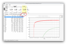
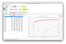
merlin, S is 10000 and ms is 10, take out the screenshot wrong
@fortyfive Place 2 diodes instead of those resistors, for the return current
@euro21 I'll have to measure the transformer parameters; the builder didn't give them to me. I think I have a lot to learn.
@trobbins
https://jelabs.blogspot.com/2022/03/emails-from-ukraine-was-radiotron-se2a3.html?m=1
@fortyfive Place 2 diodes instead of those resistors, for the return current
@euro21 I'll have to measure the transformer parameters; the builder didn't give them to me. I think I have a lot to learn.
@trobbins
https://jelabs.blogspot.com/2022/03/emails-from-ukraine-was-radiotron-se2a3.html?m=1
Yes I checked that blogspot, but your PSUD2 schematic shows a different arrangement, as the secondary voltage, rectifier type, choke and filter cap values are all different ??
PSUD2 is a benefit to look at the initial hot turn-on performance of the supply (such as diode surge peak), and the steady-state performance (such as ripple levels and diode continuous peak), and step-load performance (such as to indicate ringing if your amp can indeed cause a step load change).
Not all capacitor manufacturers provide suitable datasheets for identifying ESR - I couldn't identify anything related to Sprague-Vishay Atom, as used in the blogspot. You will need to use some engineering experience to identify somewhat similar datasheets from other manufacturers and infer a reasonable parameter value for your simulation. Imho, 100 ohm is way tooo high.
??different arrangement
caps are jj 2 2x50uf 500vchoke and filter cap values
https://www.jjtubes.eu/image/data/tcte.pdf
choke is 10H 200ma
There were those two power supply designs, that's why I want to modify it to make it as good as possible.
Ok, my mistake. I had two types of power supplies saved for the same amp.
But I made the one in the link in post #12.
In short, a Hammond 302AX.
Rectifier tube: I have two, 5U4G and 5R4GYB.
Two JJ, two 50UF 15ohm ESRs.
10H 80ohm inductors.
And the 15k resistor, which, when I play with this value, is what makes the most difference in the power supply design.
But I made the one in the link in post #12.
In short, a Hammond 302AX.
Rectifier tube: I have two, 5U4G and 5R4GYB.
Two JJ, two 50UF 15ohm ESRs.
10H 80ohm inductors.
And the 15k resistor, which, when I play with this value, is what makes the most difference in the power supply design.
The Hammond 302X data indicates the PSUD2 model should have half-winding parameters of 324V, and 62 ohm effective (using the PSUD2 calculator with 120V 3R primary and 324V 40R secondary half). PSUD2 with a 2700 resistive load (or 120mA CC load) gives 330Vdc continuous and diode 450mApk continuous, and 1.25Apk hot-start with a 5R4, which are within the 5R4 limits.
If you modify that supply to use 50uF input cap then the hot start pk increases to nearly 2A for a 5R4, and about 2.4A for a 5U4, which appear to be just within limits.
If you check the step load response, such as from 120mA to 180mA, then the original design shows no sign of damped resonance, but your proposed 50uF-10H-50uF shows up a damped resonance at about 8Hz. Note that the 2A3 amp you are interested in operates in class A, so won't exhibit step load changes on your power supply, so the resonance behaviour is somewhat mute unless your full power frequency response extends down towards 10Hz.
With respect to the 15k dropper, then for sure it will impact the steady state voltage downstream, as it is meant to do - depending on the load conditions.
- Home
- Amplifiers
- Tubes / Valves
- PSUD 6C6 2A3 amp