
thx
Franz Sh.
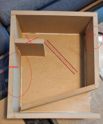
The small stiffening board looks nice, but doesn't help at all - it should be placed differently, perhaps at a 60° angle - and it may take up a little more space.
If
HBt.
Franz Sh.
The small stiffening board looks nice, but doesn't help at all - it should be placed differently, perhaps at a 60° angle - and it may take up a little more space.
If
- the driver now changes its position sensibly, the “clear” dip will also disappear. Damping material, the Visaton polyester stuff ... (or 100% cotton wadding) is a good choice
- one would like to see the port (the midrange horn!) at the front, than one can of course copy Udo's suggestion exactly, or the Alpha of the horn friends Till and Raffi !
HBt.
Attachments
Last edited:
I built Udo Wohlgemuth's version.
The board sits just right? It acts as a stiffener. I wouldn't build it the way you drew it.
The membrane is wafer-thin; the board sits much too close to the membrane.
Secondly, you can control the shrinkage by lining the side walls, at membrane height, with 1 cm of felt and inserting the polyester batting directly behind the membrane, not stuffing it, but plucking it in finely.
What we see at first glanceI built Udo Wohlgemuth's version.
The little board can stay where Udo glued it in. In the first proposal of the K&T, our Udo had not yet glued the board. He only came up with the board idea later.The board sits just right?
Naturally.It acts as a stiffener.
Of course not. You copied Udo W.'s latest suggestion.I wouldn't build it the way you drew it.
I would like you to explain this assertion in a plausible and technically correct way. There are no problems in my SPH60X box!The membrane is wafer-thin; the board sits much too close to the membrane.
Stuffing is really not a good idea.Secondly, you can control the shrinkage by lining the side walls, at membrane height, with 1 cm of felt and inserting the polyester batting directly behind the membrane, not stuffing it, but plucking it in finely.
#
I assume the author of this thread has learned everything he wanted to know.
On Udo's famous photo series you can clearly see the procedure, there the stiffening board divides exactly (pi times thumb) the back wall.
This looks completely different in the housing drawing. LS of this type are created in 5min. They are simply fun projects ..!

very similar bass reflex enclosures, the "horn" is just a tapered reflex port
Alpha is a vented box with a slot vent, the CT193 is a BigVent Reflex (BVR)
dave

I can confirm this: I lowered the range from 440hz to 2500hz by 5db with an equalizer.. I can only advise: to actively equalize your system, “you only believe it when you have heard it yourself”, of the entire spectrum.
Alpha is a vented box with a slot vent, the CT193 is a BigVent Reflex (BVR)
dave
The reflex port of the alpha opens like a mouth.
And I equalize the entire frequency range from 20Hz to 20kHz at one-third octave intervals; passively using a broadband blocking circuit (Rp=8.2Ohm, Cp=3.3µF, Lp=3.3mH) and a narrowband absorption circuit (Rs=3.3Ohm, Cs=4.7µF, Ls=2.2mH{+ 1.9Ohm}).I can confirm this: I lowered the range from 440hz to 2500hz by 5db with an equalizer.
The Visaton polyester material can be cut to size, to cover the entire inner surface and glued on flush with Pattex.
@planet10
The German Udo calls this /his vent "Horn-Reflex" or simple "Hornresonator".
This is my network - and it compensates for /the frequency range from 200Hz to 4000Hz. Of course, I won't reveal the values for omnidirectional compensation, the overall EQ-function.
My baffle has an outer width of just under 20 cm.A few details about my housing (I have found all my records in the meantime):
Width inside
16cm
Height inside
29,3cm
Depth inside
31,6cm
The BR board is 28.4cm long, the reflector 16*16cm, AH 25.6cm^2 & AM 64cm^2. The port is at the top and directly opposite the driver.
It is worth delving deeper into the subject of LS (with this at first glance simple concept, CT193 ). Where should the driver be placed and where is the best place for it? This is just one of the usual questions, because ultimately it's about sound dispersion and not just about the resulting HP, i.e. the BR-like cabinet.
Dear rebuilder, please coat the membrane completely with Visaton's coating (LTS50 is the name of this liquid stuff), including the “swivel cone” - up to three procedures are ok.
HBt.
Psst
And don't forget the rounding on the sharp-edged, narrow mouth of the port, as “stv” has already outlined. The freehand filed lens (see also Alpha) is also a good idea, practically a kind of WaveGuide. An optimized geometry can be created later and provided using a 3D printer.
Have fun with it
😎
Have you carried out extensive acoustic measurements? A correction must be based on objective, reproducible, hard facts, i.e. measurements. It does for me, so this criterion is fulfilled.I can confirm this: I lowered the range (...)
The reflex port of the alpha opens like a mouth.
Then a BVR with a steeped mouth.
dave
Is there also a VBVR, very big vent reflex, also a VLBVR, very large big vent reflex ..!Then a BVR with a steeped mouth.
dave
Let's put it this way:
with a penchant for exotic names and their various abbreviations, it's easy to get confused. A glossary would be great, with exact definitions (for use) and the physical principles.
Correction:don't forget the rounding on the sharp-edged, narrow mouth of the port, as “stv” has already outlined.
this refers to the throat, not the mouth, i.e. the inlet, not the outlet.
HBt.
@Bronkowitz

If you don't want the > 400Hz hole / or dip in the frequency response, then the driver has to be quite close to the bass reflex port-inlet. But I really like your speakers, the paintwork is great. The Alpha proposal can't be better or worse because all the essential parameters are almost identical - after all, we're talking about simple vented concepts here: Bassreflex and nothing else. And by the way, the Visaton polyester mats (green) are very effective.
All the best,
HBt.
"Der Schwalbenschwanz"
Leo Kirchner
The frontal BR port is set at a 15° angle, with a constant taper towards the outlet, while at the same time using the familiar reflection board at a 60° angle and a notch in the shape of a dovetail.
That would also be an alternative ... or a Karlson with exp aperture ... There are virtually no limits to the imagination here.
I would load that speaker in a closed box. Simulation would also be easier.
black
3 ltr.
red
6 ltr.
blue
12 ltr.
green
24 ltr.
which one do you choose?!
Sorry,
I don't understand the purpose of this thread. @Bronkowitz, Could you guide or clarify the further course of this thread?
HBt.
- Home
- Loudspeakers
- Full Range
- Enclosure for Monacor SPH-60x