Because the thread started with a small 2-way bass reflex speaker with bad midrange response to be optimized.Why not look at cabinet and port resonances with the planned low-pass filter in place?
I agree that subwoofers are far less critical, because most resonances are outside the useful bandwidth anyway.
However, it may still be useful to avoid low frequency enclosure modes.
And then I just can't stop my curiosity...
That's not how it works exactly. I have described port resonances in another reply in this thread. They are not related to the passband of the driver. They are related to the airflow velocity. When I design subs for clients Depending on what sound they are looking for. Clean and low distortion than I use damping materials on the interior. Generally a housing insulation. Dacron is nearly useless until you get a lot of mass. Too few people think about drivers as radiating on both sides of the cone. You are driving a speaker out of phase or 180 degrees different in timing into the enclosure. And cones bleed through the interior sound being produced. A few nuggets of information to think through.Question guys: Why not look at cabinet and port resonances with the planned low-pass filter in place?
Seems to me they'll only resonate if excited.
In Hornresp, once I add a low-pass to a sub with the filter wizard, resonances go bye-bye...looks like masked.
Masked look is for subs that are being used as subs, low-passed say no higher than 200Hz,
......not to a woofer trying to reach much further up (which I never fool with)
Depends on the woofer bandwidth and the enclosure dimensions.Could you make a suggestion for the specific case where the driver is at the bottom or near the bottom (one end), due to wanting to avoid floor bounce effects on the on-axis response ("on-axis" in this case being for the overall speaker rather than the woofer)?
If the lowest mode of the longest enclosure dimension is well outside the woofer passband you are lucky and there won't be any problem.
Otherwise you could try positioning the woofer at the 1/4 height of the enclosure and the port at half the height, see lower simulation example c) in post #915
I will try some more simulations using a divider board to form a tapered mass loaded offset port TL.
see my MLTL test in post #531, responses in the last graph. This MLTL is still not very much optimized, better layout simulated in post #569 and #579.
I agree that subwoofers are far less critical, because most resonances are outside the useful bandwidth anyway.
However, it may still be useful to avoid low frequency enclosure modes.
Thx!
Yep, I built one double 18" ported that was so large, about 600L if I remember, internal dimensions were producing modes.
Only sub I've ever had a problem with modes or resonances.
Thx!That's not how it works exactly. I have described port resonances in another reply in this thread. They are not related to the passband of the driver. They are related to the airflow velocity. When I design subs for clients Depending on what sound they are looking for. Clean and low distortion than I use damping materials on the interior. Generally a housing insulation. Dacron is nearly useless until you get a lot of mass. Too few people think about drivers as radiating on both sides of the cone. You are driving a speaker out of phase or 180 degrees different in timing into the enclosure. And cones bleed through the interior sound being produced. A few nuggets of information to think through.
Guess I've been lucky. As said above, the only sub I've ever had any resonances from was one above. 4 or 5 other ported sub builds have all been quite as a mouse out of band. Maybe because I build very large ports long enough to keep velocity down. And probably also due to the fact I always low-pass no higher than 120Hz, and with no lower order than 60dB oct (complementary linear phase).
I made step-by-step screenshots for an easy way to start. There are other ways to set everything up, but I still use this method, because I find it the most intuitive.What are the basic settings you are using to model these?
download hornresp from @David McBean 's dedicated site: www.hornresp.net
Extract the files from the exe-archive and copy/move them to the suggested location:
C:\Hornresp\Oh, and have a look at the hornresp thread (in the "subwoofers" forum!), of course.
Start the program and select "Help" - "Input Wizard":
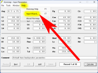
The wizard will guide you through several steps for definition of a speaker type.
The yellow highlighted selections below are essential to get the desired "offset port transmission line speaker" (driver is also offset, by the way!).
Chose 3 or 4 segments as required.
The driver is always at the end of first segment. Port is always at the start of the last segment.
Segment flare for a speaker with two parallel walls will usually be parabolic, unless there are curved walls.

The main hornresp window shows up with the standard input values.
Double click "Sd" input field to open the driver TSP input mask, type in desired values and hit "Ok"
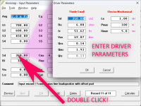
The easiest and most intuitive way to tune parameters is via the "loudspeaker wizard".
This tool allows to see results of parameter changes in real time:
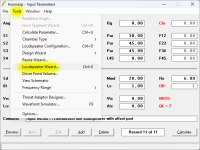
Select not to mask chamber resonances, even if that will not change much with the "offset port TL" model, brecause the enclosure is modeled as "horn segments" that will always simulate resonances - if I am not mistaken.

Adjust the desired input values by moving sliders or by clicking on the slider path and typing the desired value followed by hitting ENTER (important!).
Input values are the "horn" segment surface in cm2 (assuming a round enclosure, as far as I know, but that's a sensible approximation) and the "horn" segment length in cm.
The port surface and lenght parameters are "hidden" under the "Chamber" input parameter set (click on the "Horn S1-S4" dropdown menu).
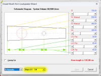 in
inWhenever useful change the graph from "Schematic" to "Power" (for SPL power disregarding directivity), "impedance" .... etc.
Change input parameters from "Horn S1-S4/5" to "Filling" or whatever needs to be changed.
With "Power" Graph selected chose to see output of driver output 1, port output 2, driver+port combined, or driver and port combined1 (combined and separate).
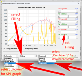
Change filling in the "Filling" input mode. I use a Flow resistivity (Fr) value of 600 (see EDIT below!) - that is a value for rather light stuffing as far as I remember.
By moving the "Tal" sliders the thickness and position of filling changes. It's very intuitive in the schematic graph but of course it makes even more sense to observe the changes in the "Power" graph.
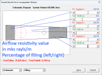
I used the default values for TSP and geometry as assumed by the input wizard, so please disregard the resulting response graph!
Also note that filling can only be modeled in the "loudspeaker wizard".
If you save the settings by hitting "Save" and then hit "Calculate" the result will be calculated without filling (after this step hornresp allows exporting the graph text file, can be renamed to "frd").
The filling parameters are still saved, however, and will show up in the "loudspeaker wizard".
I mostly use the loudspeaker wizard and make screenshots whenever necessary.
EDIT:
David McBean wrote in the hornresp thread post #13627:
Wool with a density of 10 kg/m^3 has a resistivity of 500 mks rayls/m.
Wool with a density of 100 kg/m^3 has a resistivity of 15000 mks rayls/m.
Last edited:
I made step-by-step screenshots for an easy way to start. There are other ways to set everything up, but I still use this method, because I find it the most intuitive.
An excellent step-by-step introductory description!
Select not to mask chamber resonances, even if that will not change much with the "offset port TL" model, brecause the enclosure is modeled as "horn segments" that will always simulate resonances - if I am not mistaken.
Correct.
Selecting the resonances masked option treats throat (Vtc, Atc) and rear (Vrc, Lrc) chambers as pure acoustic compliances. The chambers are not used in an offset port TL design.
The masked / not masked option can be "permanently" set using the Tools > Options menu. It is then not necessary to select the required option each time that the loudspeaker wizard is opened.
Input values are the "horn" segment surface in cm2 (assuming a round enclosure, as far as I know,
Correct.
Hornresp assumes round (axisymmetric) segments, chambers and port tubes.
By moving the "Tal" sliders the thickness and position of filling changes. It's very intuitive in the schematic graph but of course it makes even more sense to observe the changes in the "Power" graph.
The loudspeaker wizard schematic diagram can be instantly viewed from any other output window by pressing and holding the V key. Releasing the key returns to the previously-displayed window.
To expand a bit: hornresp shows and adjusts positioning in one dimension only. On a real box there is three: height width and depth.
For example considering woofer to be on a front panel it's always exactly at the end of depth dimension and maximally excites modes in the depth dimension. This one can test with hornresp by moving the driver to the end of the adjustable dimension to learn how the stuff works out. On width dimension driver is typically centered, so width dimension lowest mode doesn't get excited that much, it's also likely shortest dimension due to preference of tall and narrow boxes today, and so on.
After playing with it a while one can simulate this stuff in head. It all relates to sound wavelength, like everything in loudspeakers. So rules of thumbs emerge as already listed by stv: avoid putting port inlet or the driver to pressure node of modes. Since this cannot be completely avoided, at least watch out the lowest frequency modes (of longest box dimensions) because those are the most problematic: closest to the pass band and least affected by any damping material. Hence, positioning driver at mid of longest dimension and port inlet to a velocity node of the second lowest makes sense.
Further things to consider: box internal shape might not be symmetric so it's not exactly simple to determine what is middle of a dimension, damping material might also affect this. Also, area of a port and cone affects some, what if box is no bigger than the driver? Multiple ports might make some leakage cancel out at far field. Minimizing length of a dimension one cannot optimize positions for pushes all modes higher in frequency, and so on.
At least avoid worst possible scenario, which would be high aspect ratio box with driver on one end of long dimension and port inlet on the other. Both would be at a pressure node of lowest mode and make sure it all leaks out maximally. This is essentially what happens with a transmission line, so sometimes might be a desired effect.
There is a lot of things to consider due to application as well. For a pro audio subwoofer one might consider cooling effect of the port(s), make port part of bracing to save on weight, function to help with handling, be on side that works with unknown positioning opportunities, perhaps a niche audience expects some particular sound, and so on. On a home speaker there is no necessity for cooling, positioning is known, might be bass of a two way speaker so pass band extends way higher than with a sub etc. No one size fits all like in any aspect of speaker design.
Last edited:
This is how people should use and think with any simulation program or calculations.At least avoid worst possible scenario
For years I have seen people getting really nit-picky on details.
Problem is that even FEM/BEM methods are not even that accurate.
Or they will require so much time to setup, that you might as well build a bunch of (simple) prototypes.
If not only to see that certain things won't work in practice, something you will never ever gain from any software.
You want to get either ballpark figures, or a way to look at the problem on a relative way, so you can make educated guesses.
Hornresp won't give you 100% accurate results, but it will get you close enough to get a proper starting point.
Sure, there are always specific scenarios where it fails, but that's just the nature of the beast.
That most certainly doesn't mean it's useless (quite the opposite!)
In my opinion, people should know these things beforehand, when designing loudspeakers.
The reality is that very often form comes before function.
At least that's what I see with 90% of my clients.
So from that point of view, I totally understand mark100's response.
Avoiding is often a bit easier and (more importantly) more predictable.
Sometimes that's just not always possible.
For any 2-way, or 2,5way you're stuck in many cases.
Any bit that can help stretch a certain approach is always very useful!
Bumped into this yesterday.
Haven't read the technical papers yet, but Klippel seems to be interested in port measurements as well:
https://audioxpress.com/news/klippe...l-identification-professional-flsi-pro-module
Haven't read the technical papers yet, but Klippel seems to be interested in port measurements as well:
https://audioxpress.com/news/klippe...l-identification-professional-flsi-pro-module
Thanjs, yes, they do!but Klippel seems to be interested in port measurements as well:
This is an excerpt of an older paper, see post #97:
Interesting, these "simple" systems like transducer in a box are like onions, peel one layer to find another one 😀 So, not only port distorts but the driver as well, due to port action.
Another interesting one in Klippel article b_force linked to is Sd(x) to be added at some point.
Another interesting one in Klippel article b_force linked to is Sd(x) to be added at some point.
Yes - unless you use a big enough and optimal geometry port that provides laminar flow up to the estimated highest level.not only port distorts but the driver as well, due to port action.
Where to find such a magic port?
Here in this thread, using the port optimizer tool!
As you have experienced, such a port gets very big. I suspect most speaker ports are rather (too) small and accept some flow separation, leading to port blowing and potentially to unbalanced pressure in/outsude the box. At high levels.
Yes I am familiair with that one, in fact I think I showed this before in this topic 😉 😀This is an excerpt of an older paper, see post #97:
Give me one other practical system that has a perfect laminar flow.Where to find such a magic port?
These systems are VERY rare. Even outside acoustics.
Yeah I know, it's not relevant for this topic, so I didn't mention it.Another interesting one in Klippel article b_force linked to is Sd(x) to be added at some point.
You are right, of course.perfect laminar flow
However, it seems enough to not let the oscillating flow disrupt. Such a disruption introduces turbulence, chuffing, compression, harmonic distorsion.
With short or highly flared ports this flow disruption is more sudden and violent.
With long and non-flared ports the disruption is more gradual and maybe more acceptable (but starts earlier).
What’s actually interesting to me is that, if you dive into the literature, most of this has been known for decades.Interesting, these "simple" systems like transducer in a box are like onions, peel one layer to find another one 😀 So, not only port distorts but the driver as well, due to port action.
Yet it often gets brushed off as unimportant.
To put things back into context again: if we go back 30-50 years, many of these issues were far less problematic in classic 3-way systems.
Large cabinets, woofers with minimal cone excursion, and crossover points around 500–800 Hz.
Maybe the exception is in PA (sound reinforcement) applications, but in those cases, these details usually aren’t high on the priority list.
So when does a BR turn into TL?
In the image below:
A and B are the same bass reflex system.
C is a standard transmission line system produced by increasing L23 in system A.
D is a mass loaded transmission line system produced by increasing L12 in system B.
Increasing L12 or L23 in the following design using the loudspeaker wizard slider shows that the system transforms uniformly from a bass reflex system to a transmission line system.
Attachments
From a lumped-element model (roughly 2*fs and lower), those are all just mass-loaded systems.A and B are the same bass reflex system.
C is a standard transmission line system produced by increasing L23 in system A.
D is a mass loaded transmission line system produced by increasing L12 in system B.
But I totally understand (and agree) the practical explanation and presentation here. 👍
The real question "when does BR turn in TL" is not very easy to answer.
All depends on size of wavelength, frequencies of interest, dimensions and ratios.
The most simple answer is: It depends on how you look at the problem.
Similar to the wave–particle duality, light behaves like waves as well/or as a particle.
Fact is, there is not hard discrete line between BR vs TL.
So a BR can become more and more like a TL or vice versa.
As you have experienced, such a port gets very big. I suspect most speaker ports are rather (too) small and accept some flow separation, leading to port blowing and potentially to unbalanced pressure in/outsude the box. At high levels.
Hi stv, I likes big ports!!
60% of Sd. This is the sub that was too big for its britches....the one i said had modes....my only failure to date. Response was great until high drive levels kicked in resonances, Would take too much bracing etc to fix.
This one at 44% Sd totally rocks. 24" long port.
- Home
- Loudspeakers
- Multi-Way
- Investigating port resonance absorbers and port geometries