BURNED OUT R4
I've searched the thread and see that a few folks have had this problem, so have tried to follow their steps for resolution but am at a dead end.
Background: I had my amp up and running at .500mV offset which I let cook for 6 or so hours. Things sounded fine but not amazing, not a big step up from my ACA. I decided to try a higher offset so moved things to .600mV and let it stay there for an hour or so. I powered down and then disconnected the PSU and moved some wires around to try and manage a mild hum. I reconnected everything and powered up and both R4s flamed out, like bad. I realized I had accidentally swapped my ground and -24 supply from my PSU (oops) and figured that was the issue.
Fixes I've tried: I've reconnected everything and re-ran my dim bulb test and then turned things on with a variac in line. I still get smoke when I get the variac up around 80 or so VAC which is putting out around 15VDC from my PSU. Right now I'm just testing out one channel to see what I can get going before messing with the other one.
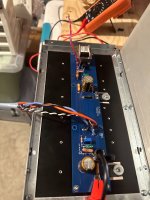
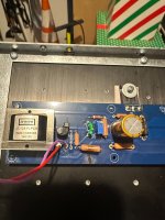
R4 is getting up to 9VDC across it before it starts to smoke which seems like WAY too high a number here. My bias is still showing 0.00mV at this point. I don't think it's any of my soldering since I had sound not so long ago. Pictures attached, appreciate any other ideas folks have for me. I'm hoping it's not the signal transformer that is trashed.
I've searched the thread and see that a few folks have had this problem, so have tried to follow their steps for resolution but am at a dead end.
Background: I had my amp up and running at .500mV offset which I let cook for 6 or so hours. Things sounded fine but not amazing, not a big step up from my ACA. I decided to try a higher offset so moved things to .600mV and let it stay there for an hour or so. I powered down and then disconnected the PSU and moved some wires around to try and manage a mild hum. I reconnected everything and powered up and both R4s flamed out, like bad. I realized I had accidentally swapped my ground and -24 supply from my PSU (oops) and figured that was the issue.
Fixes I've tried: I've reconnected everything and re-ran my dim bulb test and then turned things on with a variac in line. I still get smoke when I get the variac up around 80 or so VAC which is putting out around 15VDC from my PSU. Right now I'm just testing out one channel to see what I can get going before messing with the other one.
- Replaced R4
- Pulled R6 to make sure it was 47k and it is. Confirmed I didn't swap it with R5 accidentally.
- Reset P1 and P2 all the way to the right and checked with DMM that resistance is lowest when I do go this direction.
- Checked my transistors in diode mode with my DMM and see voltages across all 3 pins so I don't think they're gone.
R4 is getting up to 9VDC across it before it starts to smoke which seems like WAY too high a number here. My bias is still showing 0.00mV at this point. I don't think it's any of my soldering since I had sound not so long ago. Pictures attached, appreciate any other ideas folks have for me. I'm hoping it's not the signal transformer that is trashed.
Attachments

I agree. If Q4 is shorted, there is a path for lots of current to go through Q4, the signal transformer, and then through R4 to ground. Could also happen if Q3 is shorted.
High DC through the signal transformer is probably not a good thing either. Hopefully it is okay.
High DC through the signal transformer is probably not a good thing either. Hopefully it is okay.
I found this video and tested both Q3 and Q4 while connected to the PCB and they checked out. I may rerun that check to make sure all is good and/or desolder them to run it outside of the PCB. How should I go about testing the signal transformer?
Testing JFETs:
I am not sure whether the small signal transformer is safe with the DC current from a multimeter so I am not advising you to use it to test it. Hopefully someone with more knowledge of this will advise you.
If you have a signal generator and oscilloscope, you can test the transformer with them.
Just to cover all bases, did you check the voltage drop across R1 and R2? That will give an indication of the amount of current, if any, flowing through the mosfets.
buzzer/diode test is OK for signal xformers, nothing to worry about with 1mA of DC
but, better to use normal Rdc measurement (either auto or 2K range), and to write down ohmic values and post them here
if there is sliding measurement value, just wait that value goes to steady, surrounding caps topped up
according to schm ( relinked from post #1), pretty much sure way to test it is just to test primary windings and secondary windings
pin 1 to pin 3
pin 2 to pin 4
pin 5 to pin 7
pin 6 to pin 8
Update on the hum problem.
The Toroidy transformers arrived and I ordered the F5M kit with the Nelson's bipolar power supply to test different setups. My oberservations:
Transformers:
I bought the 300 VA "Audio Grade" and "Supreme Audio Grade v2". No difference to my ears.
But the normal transformer "working" sound is only hearable with the ear to the case and the recurring hum without the DC blocker is also very faint (impressive). Much better than the one from Sedlbauer.
But the hum in the woofer is almost the same.
Nelson's bipolar power supply:
The hum is less but still there with my ear near the woofer.
F5M with unviversal power supply:
Only a faint hum with my ear to the woofer.
Maybe it's okay to have a little hum?! I mean, it is not noticeable from say 1 meter distance with speakers with 87 dB sensitivity. Or should there no hum in a correct setup?
Question regarding the bias: The bias of the F5M is much more stable. About 1/10 of the F6 fluctuation (50 mV vs 5mV). is this because of the design?
Maybe it's okay to have a little hum?! I mean, it is not noticeable from say 1 meter distance with speakers with 87 dB sensitivity. Or should there no hum in a correct setup?
No it's not ok , you should have no hum at all
have you measured the AC voltage ( in mv ) and frequency at the speaker output ?
.
No I haven't.
Right now I run the F5M and they have almost the same symptoms. And there is a little AC on the output with nothing connected to the input (0.47 mV) and the input grounded (0.14 mV). This correlates with the hum loudness.
Right now I run the F5M and they have almost the same symptoms. And there is a little AC on the output with nothing connected to the input (0.47 mV) and the input grounded (0.14 mV). This correlates with the hum loudness.
So that I understand, the physical hum from transformers is now almost completely gone with the new transformers? If so, then the only additional thing you could I would be to add another layer of damping and isolation between transformers and chsssis. Without hearing your amp, I nonetheless suggest that this additional step is unnecessary.
Thus, the only hum remaining us from the speaker? If so, then there are multiple possible culprits but you seem to have addressed almost all of them. The level you measured seems to be to large; I recall N Pass suggesting in F5 article that 100 mv is acceptable but you could strive for 50mv. I will have to look that up so don’t rely too heavily on my recollection in this regard.
Three additional actions you could take (listed in the order to be attempted):
1. Verify all grounds and make sure your star ground has been implemented correctly.
2. Add a mu-metal or steel shield, tied to chassis ground, to protect the F6 signal transformer on the PCB.
3. Add one more stage of either RC or LC power supply filtering. If I am not mistaken, TungstenAudio used relatively small value (40-60uf) polypropylene motor run caps in metal cans to provide an additional stage of filtering in an F6.
Just to cover all bases, did you check the voltage drop across R1 and R2? That will give an indication of the amount of current, if any, flowing through the mosfets.
buzzer/diode test is OK for signal xformers, nothing to worry about with 1mA of DC
but, better to use normal Rdc measurement (either auto or 2K range), and to write down ohmic values and post them here
if there is sliding measurement value, just wait that value goes to steady, surrounding caps topped up
according to schm ( relinked from post #1), pretty much sure way to test it is just to test primary windings and secondary windings
pin 1 to pin 3
pin 2 to pin 4
pin 5 to pin 7
pin 6 to pin 8
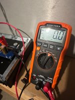
Fired the amp back up after work today and everything is looking okay (I think), except for the voltage through R4.
Got the variac up to roughly 80 VAC coming in:
- The PSU is rigged up as dual mono so was able to test both sides of the PSU since I only have one channel connected. Got the PSU up to +15.2/-15.5VDC on the loaded channel. Unloaded PSU side hit +16.6/-16.6. I expected the unloaded side to be a higher voltage but I'm surprised to have the loaded side uneven between negative and positive rails.
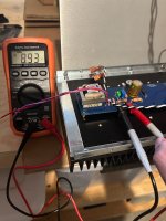
- Was able to bias things up some since I had cranked the pots all the way down. Got to 300mV across R2
- R1 was right around 300mV across it, DC offset was 2mV or so
- R4 was still dropping 7V or so still. It dropped as I raised the bias but raised as I increased the Variac as expected
- After shutting things down I ran a checks in diode mode on my DMM across both JFETs and those all had continuity
- I also ran checks against the transformer as suggested by Zen Mod. All windings had continuity and had 15 ohms resistance on the 1,2,3,4 side and 30 ohms resistance on the 5,6,7,8. Seems in line with the expected DC resistance on the datasheet for that piece.
- The one thing that really caught my eye is that the transformer was HOT.
Attachments
Please explain your methodology and results for these tests. We may simply use different terms, but I don't associate "continuity" with a result from a diode test, and I likely would have taken 6 total measurements: 3 for the N channel and 3 for the P channel before possibly pulling the JFETs and checking them out of the circuit.After shutting things down I ran a checks in diode mode on my DMM across both JFETs and those all had continuity
I'd be absolutely certain that both JFETs are functioning properly prior to looking for other causes / issues. A faulty JFET seems likely, and I haven't seen it ruled out definitively yet. Maybe I'm paranoid... or missed a result somewhere else.
Fair fair. To clarify my process - set my DMM to ohm meter setting which also gives quite an annoying buzz when there's continuity between two points. Tested the JFETs as follows
The ohm reading on the N channel is lower than expected based on the videos Ben Mah posted above. Maybe the N channel is bad? I have 4 more of those laying around right now so would be easy to swap out for a clean set
- Q3 (N Channel): Gate to source - annoying buzz and 9.4 ohms
- Q3 (N Channel): Gate to drain - annoying buzz and 9.4 ohms
- Q3 (N Channel): source to drain - annoying buzz and 0.5 ohms
- Q4 (P channel): Drain to source - annoying buzz and 30 ohms
- Q4 (P channel): Gate to drain - annoying buzz and 40 ohms
- Q4 (P channel): gate to source - annoying buzz and 10 ohms
The ohm reading on the N channel is lower than expected based on the videos Ben Mah posted above. Maybe the N channel is bad? I have 4 more of those laying around right now so would be easy to swap out for a clean set
Did you remove the JFETs from the board before testing? Results are not valid when the JFETs are connected to together and to components on the board.
@Calvdart - Thank you for clarifying. That's not what I thought you meant by a "diode test". I thought you may have set your DMM to "diode mode", which is also a valid test, and may also indicate failure. Your resistance results are valid, but they may not be not definitive.
You may know this, but JFETs are 'normally closed'. Until you apply a voltage at the gate and start to restrict the current from drain to source / and vice versa, you will have relatively low resistance. They also tend to fail 'closed', so a simple "beep test" won't tell you much. With the actual resistance, we can gather a bit of information. Your N channel source to drain resistance looks suspect. It should be up in the 30 to 40ish Ohm region even in circuit. As we've mentioned, if they're not working properly, then you'll have much more current than expected running right through your transformer to GND which is why R4 burns up and your transformer gets hot. There's nothing there to restrict that current.
You have a working board for comparison, which is always wonderful to have. Check your working board for comparative measurements.
Take your DMM set to diode mode and check the forward voltage in those positions. Probe orientation can be important. If you're unsure, just flip your probes at each point.
Here's an example of some measurements using the diode test (along with checking the resistance) that would give me some confidence that I may not need to pull the JFETs. If I were simply doing it, I wouldn't run every combination, this is just for illustration.
N Channel - Q3
G/S - 0V7
S/G - 0V7
G/D - OL (LED should light up on left channel)
D/G - 0V7
S/D - 0V04
D/S - 0V04
P Channel - Q4
G/S - 0V7
S/G - 0V7
G/D - 0V7
D/G - OL (LED should light up on right channel)
S/D - 0V04
D/S - 0V04
I try to take as many meaningful measurements in situ as I can before yanking parts. Above took me < 1min to do for both boards.
Sadly, I'm pretty sure that your Q3 is dodo. Why did I think that even before you posted measurements and suggested that you check your JFETs? If you draw a path from the positive rail through Q3, through your transformer windings, through R4 and to GND... voila. If Q3 is fully open (not working), that's what happens. Since it was working to begin with until you swapped your rails, that seemed to be the most likely culprit. Your resistance reading all but confirms it.
What I'd do (but it may not be what you'd do) just for safety sake and because they need to be matched... is replace both.
That's one idea... one person. There could be other things to validate, but as I mentioned above... that's where I'd start.
Since you have to take them out, you can certainly check them once you remove them to confirm or debunk any suspicion.
Last edited by a moderator:
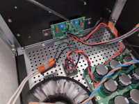
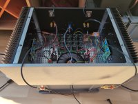
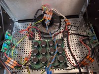
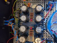
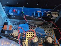
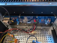
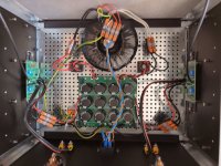
@Zen Mod here are the pics of the F6 and F5M
@Halauhula
1. Verified (I think)
2. I could but I have the same Problem with the F5M
3. I will buy some the next time I come around the shop
@Halauhula
1. Verified (I think)
2. I could but I have the same Problem with the F5M
3. I will buy some the next time I come around the shop
Attachments
-
 IMG_20250414_100804_995.jpg405.7 KB · Views: 38
 -
 IMG_20250414_100808_784.jpg438.6 KB · Views: 35
 -
 IMG_20250414_100812_692.jpg370.8 KB · Views: 35
 -
 IMG_20250414_100821_553.jpg529.2 KB · Views: 30
 -
 IMG_20250322_171047_421.jpg432.2 KB · Views: 31
 -
 IMG_20250322_171036_432.jpg400.6 KB · Views: 34
 -
 IMG_20250322_171039_727.jpg386.3 KB · Views: 32
 -
 IMG_20250322_171031_924.jpg491.3 KB · Views: 32
 -
 IMG_20250414_100801_672.jpg406.8 KB · Views: 40
Alright, a few weeks later and way more hours of work then I'd prefer, I'm back in business.
I ordered another matched pair of JFTETs from the store and swapped those in, and everything powered up as expected. R4 had a few dozen mV dissipated across it, way better than the 7V I was seeing before. Can't wait to listen to some sweet sweet music on a Friday evening to celebrate.
I ordered another matched pair of JFTETs from the store and swapped those in, and everything powered up as expected. R4 had a few dozen mV dissipated across it, way better than the 7V I was seeing before. Can't wait to listen to some sweet sweet music on a Friday evening to celebrate.
- Home
- Amplifiers
- Pass Labs
- F6 Illustrated Build Guide