Hello everyone, I've recently bought the quad 33 and 2 of the 303 power amplifiers. Since the 303 do not have an on/off switch do thay permanently stay on?
Thay are connected via a 4pin din into 33 which is then split into 2 4pin din for each 303. Power is a 3pin din into the 33. One 303 has a 3pin din power and the other has a kettle lead 3pin power cable. Is this correct.
Advice needed on how to connect/use as mono blocks.
Thay are connected via a 4pin din into 33 which is then split into 2 4pin din for each 303. Power is a 3pin din into the 33. One 303 has a 3pin din power and the other has a kettle lead 3pin power cable. Is this correct.
Advice needed on how to connect/use as mono blocks.
I'm guessing due to each 303 having it's own 4pin din inputs, each 303 will output a left and right.
Regarding the 303's lack of on/off switch and having them on all the time, I worry about feedback from other sockets around the house which cause pops and thuds audible through the speakers. Ive read but have never used the switched inputs at the rear of amplifiers and pre-amps that can switch equipment on and off when the amplifier/pre is switched on and off. Is this a solution?
I will post pics of amplifiers and cables I have
Looking at the specs: the 33 has an output impedance of 1K ohm, with a recommended load of 10K ohm or more. The 303 has an input impedance of 22K ohm, so driving two from one 33 would halve this to 11K ohm, just within the limits, and should therefore work with the split lead as you described. I would always switch the amps off at the wall socket when not in use - why age the equipment unnecessarily.

I'm guessing due to each 303 having it's own 4pin din inputs, each 303 will output a left and right.
The 303 is a stereo power amplifier and not a monoblock amplifier.
I think you mean that the 33 and one 303 has a 3 pin Bulgin mains socket:
The 303 has no on/off switch. I read it was plugged into the switched mains outlet on the back of the 33.
P.S. You can buy switched 13A plug tops to isolate the power amps from the mains if necessary:
Bridged is not a good idea I take it?
Thay will have to be identical and balanced, which they are not.
Is there any reason why one would have connected them this way? ie two 303's into the 33
Thay will have to be identical and balanced, which they are not.
Is there any reason why one would have connected them this way? ie two 303's into the 33
Bridged is not a good idea I take it?
I read that the two speaker outputs of a Quad 303 "should not be paralleled without incorporating some form of current sharing network".
You would need expert advice on that.
Is there any reason why one would have connected them this way? ie two 303's into the 33
This may be done for bi-amping purposes as explained here: https://myoldvintagehifi.blogspot.com/2012/02/bi-amping-quad-303.html
Galu, I was reading this exact page yesterday!!
I like to research as much as I can before asking you guys for ultimately the final decision.
I like to research as much as I can before asking you guys for ultimately the final decision.
I've been reading up on converting a vintage 303 stereo power amplifier into a monoblock:
One method is bridging, which needs a phase inversion on one input.
Another method is parallel where there is usually a small resistance in line with each output to balance the current from each output.
Bridged increases voltage output, parallel increases current output.
Here's more reading for you: https://en.wikipedia.org/wiki/Bridged_and_paralleled_amplifiers
I found this:
"The only advantage from parallel mono operation is increased current into 4 ohm loads.
I wouldn't recommend it since to work well it requires the ability to fine trim the input signal on both channels for perfect balance, so you need to start adding potentiometers.
There is a far easier way to make a 303 into a mono amp and improve it's performance - remove one of the driver boards.
The 303 uses a regulated power supply and this allows each channel of the 303 to supply around 3 amps maximum. By removing (or disconnecting the power lines) to one channel you allow the remaining channel to use the entire capacity of the regulated supply.
Unless using 4 ohm loudspeakers the single channel 303 should play just as loud as the parallel version, will perform better and not require further modification.
The 303 is not suitable for conventional bridging unless you were using 16 ohm (or greater) loads."
The above information is courtesy of Rob Holt in post #20 of this thread: https://www.audio-forums.com/threads/quad-303-blew-up.111842/
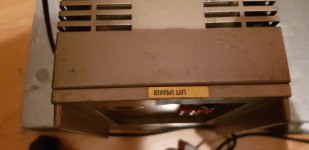
One main reason for asking about mono blocking the 303's is because on one 303 the previous owner has a sticker on it (left speaker).
I don't know if there is any internal modification. I shall show you all the cables that came with the amplifiers.
Give me 20mins
I don't know if there is any internal modification. I shall show you all the cables that came with the amplifiers.
Give me 20mins
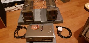
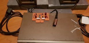
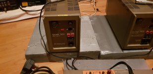
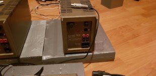
This is what I have. One 303 has blue caps with connections on the top. Other has no connections ontop of caps. I'm waiting on delivery for another 3pin din power cable. And the board is there but I don't know what it is for.
Attachments
-
 20250326_170603.jpg209.7 KB · Views: 40
 -
 20250326_170653.jpg206.3 KB · Views: 34
 -
 20250326_170434.jpg282.9 KB · Views: 39
 -
 20250326_170452.jpg226.3 KB · Views: 41
 -
 20250326_170501.jpg276.5 KB · Views: 39
 -
 20250326_170504.jpg241 KB · Views: 40
 -
 20250326_170525.jpg212.9 KB · Views: 41
 -
 20250326_170543.jpg166.9 KB · Views: 32
I'm waiting on delivery for another 3pin din power cable.
Don't you mean a 3 pin Bulgin power cable?
Those pictures are not of much help. You would have to open up the 303 marked "LEFT SPEAKER" to look for evidence of a modification like one of those referred to earlier.
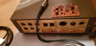
Here's a clear indication of what's on the back of the 33 preamplifier:
Note the facility to accept plug-in printed circuit boards, so that may explain the mystery board you have found.
Am I correct in presuming that there is no way to contact the previous owner?
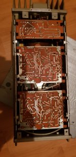
Yes no way...baught from an auction house and do not know the history, I mite just phone and ask, why not, no harm in asking. I did open the bottom of the amplifier that has no left right designation and saw 3 boards underneath but stopped there. The amp market 'left' , the caseing is a tad looser than the other which indicates it has been opened so I will look inside.
So what to look for?
I shall take pictures
So what to look for?
I shall take pictures
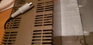
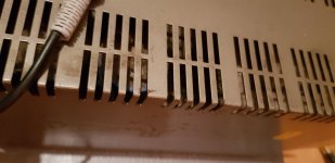
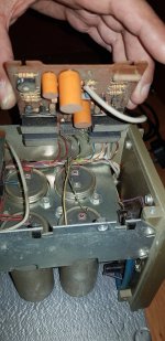
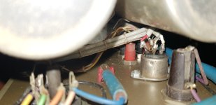
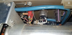
So the 4 large caps are upside down in the "Left" amp. All 3 boards are present on the underside of the amplifier.
So what to look for?
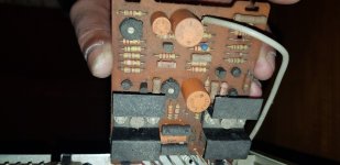
I'd start by looking for evidence of an added potentiometer at the 303 input as indicated in the Parallel Connection diagram at the top of your PDF.
Alternatively, there may be a phase inversion transformer in that position as indicated by the Series Connection diagram at the bottom of your PDF.
For reference, this circuit shows how transformer bridging is performed:
Note that in this method, the loudspeaker is connected across the two positive (red) speaker output terminals.
Last edited:
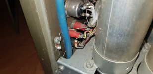
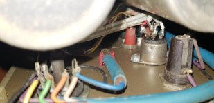
Inside
Attachments
-
 20250326_184712.jpg400.1 KB · Views: 29
 -
 20250326_184727.jpg344.5 KB · Views: 28
 -
 20250326_182527.jpg298.2 KB · Views: 29
 -
 20250326_182607.jpg276.1 KB · Views: 32
 -
 20250326_181942.jpg297.2 KB · Views: 27
 -
 20250326_182612.jpg240.5 KB · Views: 30
 -
 20250326_182807.jpg245 KB · Views: 27
 -
 20250326_182758.jpg260.5 KB · Views: 29
 -
 20250326_182833.jpg368.3 KB · Views: 30
- Home
- Amplifiers
- Solid State
- How to connect QUAD 33 to 2×303s (Vintage)