
Thanks Jan.
That's what shows up on most other sites as an avatar, so I figured I would make them the same.
That's what shows up on most other sites as an avatar, so I figured I would make them the same.
Ok, I see. I still wonder about the GND symbol, though. Pin-1 is the RTX chassis, not part of the audio signal. What's the purpose of connecting C2/R3 and C6/R6 to pin-1?I updated the drawing with pin numbers for the XLR connector
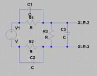
Jan, if the amplifier should be loaded with approx. 100 pF, I guess the capacitor values in your circuit would be C1 = C2 = 200 pF and C3 = 40 nF (for 1:100 voltage attenuation), correct?
(The RTX input capacitance of 40 pF will be negligible compared to C3.)
What about R3? Is this the input resistance of the RTX (200 kOhm)? Something else? Why?
(The RTX input capacitance of 40 pF will be negligible compared to C3.)
What about R3? Is this the input resistance of the RTX (200 kOhm)? Something else? Why?
Jan- Thats a good simulation, however without a gnd the simulation won't run and if there is DC at play or significant common mode the RTX input can get fried. I'm speaking from old experience.
Divide by 100 would get 10V at the RTX which is a safe range. The RTX inputs are 100K to ground for + and - and 40 pF to ground for + and -. I don't know what the actual input C value is. If there is significant common mode Jan's circuit will pass that to the input attenuated by the internal impedance. DC will not be attenuated. R2, R5, C3, C7, C4 and C8 are the internals of the RTX.
Divide by 100 would get 10V at the RTX which is a safe range. The RTX inputs are 100K to ground for + and - and 40 pF to ground for + and -. I don't know what the actual input C value is. If there is significant common mode Jan's circuit will pass that to the input attenuated by the internal impedance. DC will not be attenuated. R2, R5, C3, C7, C4 and C8 are the internals of the RTX.
For DC/LF the attenuation is 1/2.R3/(R3+R1).
For HF the atten is (1/2.C3)/(C3+C2).
For max CM performance, the source impedance should be accounted for in R1 and R3 and C1 and C2, and the load impedance (analyzer) should be accounted for in C3 and R3. This is something that needs to be accounted for in any attenuator, especially at high atten factors. This is not specific to bal attens.
Example: if you calculate C2 to be 100pF and the analyzer is 40pF, select C2 as 60pF.
That also means that if you want to use it with another analyzer with a different Cin or Rin, you need to adapt that.
You can connect XLR pin 1 as suggested by the AES standard, to chassis only, at the input connector.
Edit: corretion of text.
Jan
Last edited:
For simulation, just connect the source to ground through 50Meg or whatever. It's just to satisfy LTspice, not for the functional operation.Jan- Thats a good simulation, however without a gnd the simulation won't run and if there is DC at play or significant common mode the RTX input can get fried. I'm speaking from old experience.
And you can always add DC blocking caps, that's not essential to the circuit.
Edit: does the RTX have DC blocking?
Jan
Last edited:
The whole point of a balanced input is that the commom mode is allowed to float within the power supply limitations of the input stage. Remember, you do not want to introduce any ground reference, which would introduce hum and noise. Although, with non-state of the art analyzers the difference may be insignificant.If there is significant common mode Jan's circuit will pass that to the input attenuated by the internal impedance. DC will not be attenuated.
Jan
Sorry, there are some errors in my post # 3327, some parts designations are swapped.
DC/LF atten is 0.5.R3/(0.5.R3+R1)
HF atten is 2.C3/(2.C3+C1)
Analyzer Rin should be subtracted from calculated R3 value.
Analyzer (and cable!) Cin should be subtracted from calculated C3 value.
Source output R and C should be subtracted from calculated C1 and R1 values.
Some of these values can be ignored in some cases. For instance, a 10 ohms opamp source Rout will only cause a 1% error on a 1Meg R1 in a 100:1 atten.
If both chains are identical, it would change the calculated atten from 100:1 to 101:1, not something to lose sleep over.
Important for CM performance is that the impedances in both chains are identical, so it may be worthwhile to match parts.
Remember, a 1% mismatch in atten between the two chains limits your CM rejection to 40dB only.
Jan
Last edited:
Ok, this is what I don't get. What do you mean by "accounted for"? What is the function/purpose of R3? I believe R3 in your schematic represents the input resistance of the RTX (200 kOhm), but I am not sure. I may have a blind spot, and maybe you did not explicitly show the RTX input resistance on your schematic at all, and R3 would be something else. Once I understand what your R3 really is/does, the pieces (and especially the function of R1 and R2) should come together in my brain. Can you shine some light on this?...and the load impedance (analyzer) should be accounted for in ... R3.
For DC/LF, your atten has two rersistors: series (R1) and parallel (R3).
But if you attach an anlyzer, it's input R appears in parallel to R3.
So to keep the correct calculated atten, the analyzer Rin in parallel to R3 should come out to what you calculated.
That means that R3 should be increased to compensate for the extra parallel resistance load of the analyzer Rin.
Do an example calculation and you will see it. No Rocket Science.
With my high voltage 1000:1 attenuator I also included the capacitance of the XLR cable between the analyer (100k // 200pF of the AP analyzer) input.
That cable has a label saying 'to be used with bla bla'.
There;s a similar label on the atten 'use only with cable bla bla '.
Compared to precision instrumentation, audio is easy 😎
Jan
Ok, then why use R3 at all? It could simply be deleted. This would result in C3 being in parallel with the input impedance of the RTX (200 kOhm || 20 pF).For DC/LF, your atten has two rersistors: series (R1) and parallel (R3).
But if you attach an anlyzer, it's input R appears in parallel to R3.
Since C3 >> 20 pF, we can ignore the capacitance of the RTX input, so C3 will not need any change due to the RTX load.
R1 and R2 (parallel to C1 and C2) might be useful to mirror the R-C impedance curve of the RTX+C3 in the AC domain (using the same RC time constant).
I don't see why I would need to worry about DC attenation since I care about AC signals only. The amplifer output terminals will be within 10 VDC relative to chassis-GND. The DC voltage across the terminals will be roughly 1 V or so. Am I missing something about DC?
So, as a worked example:
- total capacitance seen by the estat amp should be 100 pF ==> C1 = C2 = 200 pF
- AC voltage attenuation = 100x ==> (1/C3) / ( 1/C1 + 1/C2 + 1/C3) = 1/100 ==> C3 = approx. 10 nF
- RC time constant of C3+RTX input input = 10 nF x 200 kOhm = 0.002 s ==> R1 = 0.002 s / 200 pF = 10 MOhm
Thoughts? What would be the advantage of this over my earlier idea of a C-R-C voltage splitter?
First of all, a capacitive voltage divider for 1:100 or 1:1000 implies impedance ratios of 1:100 or 1:1000 between the different "legs". The center cap (C3) will therefore need to be roughly 100x to 1000x larger than the outer caps C1 and C2, which in turn are 200 pF.You said: Since C3 >> 20 pF, we can ignore the capacitance of the RTX input.
Did you check or is it just a gut feeling?
Secondly, take a look at my calculation. C3 came out as 10 nF, which is 500x more than 20 pF.
I am simply trying to understand your advice by asking questions and hinting at how I understand your comments, hoping to clear out possible misunderstandings. If this is what you consider speculation, fine. Otherwise I am happy to be illuminated.You seem to spend lots of time on wild speculation without any actual calculation.
OK; why are the outer caps 200pF? At 20kHz, that's about 40k impedance.
What would you suggest for R1?
Jan
What would you suggest for R1?
Jan
Take a look at the numbers/calculations in post #3333.
The typical load of an estat headphone is about 100 pF, and that's what the amplifier should see during testing. The total capacitance of the test jig as seen by the amp is the series connection of C1+C3+C2. Since C3 is much larger than C1 and C2, the total capacitance is determined by C1+C2. For C1 = C2 = 200 pF, the resulting capacitance of C1+C2 in series will end up to 100 pF.
The typical load of an estat headphone is about 100 pF, and that's what the amplifier should see during testing. The total capacitance of the test jig as seen by the amp is the series connection of C1+C3+C2. Since C3 is much larger than C1 and C2, the total capacitance is determined by C1+C2. For C1 = C2 = 200 pF, the resulting capacitance of C1+C2 in series will end up to 100 pF.
OK, I see where you are coming from.
A C1, C2 of 200pF is a very low impedance across R1, R2 and it will decrease the atten impedance very quickly if you go up a bit in freq,
I would design the atten with as high impedance as possible, and then you can load the amp with whatever you like without being locked in to one specific case. In general, you want test equipment to be as 'invisible' as possible.
I would start at the output end and size C3 to the RTX input C and the cable C. Derdicate a cable to the atten. to always have the correct value.
Then work backwards to size C1, C2, and then from that size R1, R2 to try to keep the constant impedance to as high freq as I can.
But that's just me.
Jan
Ok, that's a fair point. The dummy load and the voltage splitter for probing with the RTX does not have to be the same circuit. I'll think about this a bit more.
In the meantime I built the contraption on the attached photo. The black wires on the outside are the amplifier outputs. The red/blue banana plugs are the hot/cold pins of the RTX. The circuit is that of post #3324 with C1 = C2 = 200 pF, R1 = R2 = 9.9 MOhm, C3 = 10 nF, and R3 = zilch.
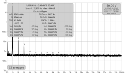
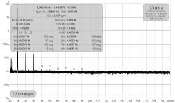
The AC voltage attenuation into the RTX works fine, but comparing the distortion measurement with a direct measurement shows some differences. With a 50 VAC fundamental from the amplifier, the 2nd harmonic is measured as follows:
In the meantime I built the contraption on the attached photo. The black wires on the outside are the amplifier outputs. The red/blue banana plugs are the hot/cold pins of the RTX. The circuit is that of post #3324 with C1 = C2 = 200 pF, R1 = R2 = 9.9 MOhm, C3 = 10 nF, and R3 = zilch.
The AC voltage attenuation into the RTX works fine, but comparing the distortion measurement with a direct measurement shows some differences. With a 50 VAC fundamental from the amplifier, the 2nd harmonic is measured as follows:
- 2nd = 0.026% if measured with the RTX connected directly to the amplifier terminals.
- 2nd = 0.047% if measured with the RTX connected across C3.
Attachments

- Home
- Design & Build
- Equipment & Tools
- DIY Audio Analyzer with AK5397/AK5394A and AK4490