Can’t be as 1N581x diodes are 1A rated Schottky diodes. Normally one checks parameters and sees a 1A diode is not the right one for a 3.25A load. Checking/comparing parameters is to avoid mounting tractor wheels on a car and vice versa. To avoid even hotter diodes than the previous ones.
The time has come to decolonize electronics I see.
“Hey! Stupid things like V and A, make exact knowledge go away!”
“No more math & gibberish, tube pilots use the parts they wish!”
The time has come to decolonize electronics I see.
“Hey! Stupid things like V and A, make exact knowledge go away!”
“No more math & gibberish, tube pilots use the parts they wish!”
Last edited:
@jean-paul
That's why I included 1N581x series as an example to illustrate that "old" type Schottky diodes forward voltage (thus dissipation) is more than modern ones.
Should at least decide, how big the diode case. From this probably can guess what type they used.

That's why I included 1N581x series as an example to illustrate that "old" type Schottky diodes forward voltage (thus dissipation) is more than modern ones.
Should at least decide, how big the diode case. From this probably can guess what type they used.
Ah OK. Still Uf of old Schottky diodes is lower than that of standard diodes under full load.
Last edited:
I got hold to the guy who originally built it and he said his memory was they were Shottky slow recovery diodes, I will pull one off and have a proper look.
Thanks for the help
Rich
Thanks for the help
Rich
With a bit more awareness now, do you still need to change the diodes you have been using?
Your initial opening view that they look like they were getting hot appears to be deficient in evidence. The pcb doesn't appear to be heat stressed.
The pcb likely provides a large % of the diode's thermal dissipation through conduction. If you change the pcb you could be degrading the cooling capability.
Are you using a tuned snubber on the incoming Vac to the diode bridge?
I have not got a snubber on currently, it is just diodes then CRC filter as it was installed originally.
I have used a 200nF and 10R in the past on other projects as an approximation based on this article/advice. https://diyaudioheaven.wordpress.com/tutorials/power-supplies/snubbering/
Is it possible to measure the noise on the 211 valve while it is running, I was concerned that the GND of the probe would create a short, and I am not sure how to provide a floating measurement, as I have not done this before.
I am trying to find my IR meter to see if I can measure anything on the overheating question.
For my education if you look at diode specifications and look for Vf and see the plot of this at a variance of Tj, how would you know what the Tj would be for a particular case?
e.g. Will the Tj always get hot to say 125 DegC in normal use and the 25 DegC is on start up and the 175 DegC is on overload?
e.g. Will the Tj always get hot to say 125 DegC in normal use and the 25 DegC is on start up and the 175 DegC is on overload?
Uf depends mainly on load current. Oversimplified: with higher current higher Uf so higher Tj.
Stuff that is powered off is at ambient temperature.
There just is no free lunch when having AC to DC conversion at 3,25A load current. Our grand dads had a very efficient and adequate solution for this in their tube amplifiers.
Please take a look at Tombo56’s very nice ultra low drop soft start R25 regulator if you want to have it fancy and a complete solution. It has the ideal rectifier builtin. A welcome feature is that fluctuating mains voltage is not a concern anymore. It is expensive to build, has way too good properties for simple filaments, does a very good job in class D amplifiers so exactly the right candidate.
Last edited:
It takes a bit of a learning curve on heat dissipation from solid state devices - perhaps well worth your while spending a few days to read through as many documents/books/tutorials/manufacturer white papers etc to initially answer your queries. It can certainly get technical, but that seems to be the path you want take.
The quasimodo threads in the power supplies sub-forum are worthwhile also going through to appreciate how to manage diode related noise and what benefit, or not, may be achievable from changing diode.
The quasimodo threads in the power supplies sub-forum are worthwhile also going through to appreciate how to manage diode related noise and what benefit, or not, may be achievable from changing diode.

Measured the Diodes with my IR gun. They are orientated vertically and so each diode sits above the next, the top diode getting the hottest
D4Top =80 DegC, D3 65 Deg, D2 50 Deg C, D1 40 Deg C
How does that sound, assuming the IR gun is correct
D4Top =80 DegC, D3 65 Deg, D2 50 Deg C, D1 40 Deg C
How does that sound, assuming the IR gun is correct
Correct. It helps to keep distance between them and having distance to the PCB for unobstructed air flow. Also to bend the highest one a little further. They have been placed incorrectly but that is just like that. Drilling the holes will help to create air flow from another direction.
Measurements should be done after about 30 minutes operation.
Temps as they are are not shocking but less warm D3/D4 would be good.
Measurements should be done after about 30 minutes operation.
Temps as they are are not shocking but less warm D3/D4 would be good.
Last edited:
Thanka for all the advice,
These were taken after 45 mins, so should be good.
Once I find out what they are I will get some new ones with longer legs and get some air around them.
They are located vertically, as shown from this view of the underside of the amplifier, so drilling the PCB will not help much
These were taken after 45 mins, so should be good.
Once I find out what they are I will get some new ones with longer legs and get some air around them.
They are located vertically, as shown from this view of the underside of the amplifier, so drilling the PCB will not help much
Attachments
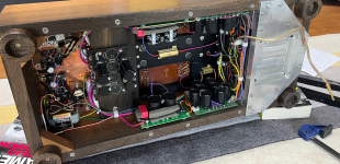
It will! There will be an extra path per diode for air drawn through the space between wooden side and PCB. It will work together with elevated mounting of the diodes (again creating an extra path to loose heat to the environment). They have indeed been mounted the least optimal way for even heat transfer.
What they are? They are rectifier diodes of the 5 to 10A kind. What type the diodes are?
What they are? They are rectifier diodes of the 5 to 10A kind. What type the diodes are?
Last edited:
I would profer that it may be worth showing a photo of underside of that PCB. Better heat transfer to ambient may be achievable by custom addition of copper sheet to diode pads, and using conduction first, rather than just convection, to transfer heat to ambient.
Assuming the IR temp was of the surface of the plastic encapsulate of each diode (IR guns likely have a spot size larger than a diode), then could guesstimate the junction temp as a slightly higher value.Measured the Diodes with my IR gun. They are orientated vertically and so each diode sits above the next, the top diode getting the hottest
D4Top =80 DegC, D3 65 Deg, D2 50 Deg C, D1 40 Deg C
How does that sound, assuming the IR gun is correct
Designers likely ballpark for a Tj below 100-120C, given a max rated Tj of 150C, and range of anticipated ambient. D4 seems to be significantly below 100C, but you have described the ambient environment.
So far you haven't assessed the operating current, or its waveform, or identified the diode, or the conduction paths on the pcb, so lots of variables before honing in on a better awareness. D1 is obviously isolated thermally with a lower local ambient, and likely less thermal conduction along tracks.
- Home
- Amplifiers
- Tubes / Valves
- How to calculate heating of Diodes