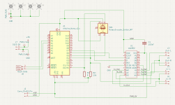
I managed, with some help from AI, to create this schema for a digital volumecontrol, using a DS1802, Arduino Nano and a rotaryEncoder.
It will be connected to either a OLED display or a 2 x 16 LCD, have the code for both.
Does it look correct ?
Have i missed something ?
It will be connected to either a OLED display or a 2 x 16 LCD, have the code for both.
Does it look correct ?
Have i missed something ?
Attachments

Hi. I'm not familiar wirh ds1802, but about arduino - you should leave d0 d1 digital ports alone, don't connect anything to them. They are rx tx ports, used for code uploading over USB, also useful when debugging code and send variables through serial port, to view them in serial monitor in arduino ide.
Also about rottary encoder connection.
If it contains a push button and two switches, connected one by one while rotatong, you can use regular digital portas like d2 d3 d4 etc for encoder connection, and use input internal pullup defining in code, internal pull-up resistor inside cpu will be turned on then and used, less parts count. Now you have pushbutton connected without external pull-up, but maybe you plan to enable it in code?
Ahh, will change the pin and use D2 & D3 instead.
The rotary is: Rotary encoder,code switch EC11 audio digital potentiometer,with switch,5Pin
Here's the arduino code:
https://pastebin.com/raQEYegj
The rotary is: Rotary encoder,code switch EC11 audio digital potentiometer,with switch,5Pin
Here's the arduino code:
https://pastebin.com/raQEYegj
Can't comment the code, as i'm not that good programmer 🙂 you should try to breadboard that, check pin connections match definitions in code, and check what issues you will have. If you wish to use save memory , volume position, or etc, i would recommend to use external eeprom ic for this. Regardless the fact, that arduino has portion of memory , reserved for store and load settings , this can easily wear out, while saving to memory each change in volume control, and make processor with code unusable. With external chip in socket, you can easily fix that. As example 24c01 24c02 etc. Offcourse , with internal eeprom is easier, but ... Also when doing code update, reflashing, this region of arduino by default also gets erased, so your stored setting gets zeroed too.
Sure i will test it on bradboard and make sure everything work as i want.you should try to breadboard that, check pin connections match definitions in code, and check what issues you will have.
No, dont want to save anything, i start from default everytime i turn the amp on.If you wish to use save memory , volume position, or etc, i would recommend to use external eeprom ic for this.
But thanks for the headsup anyway
Ok, but do you plan to restore what volume / balance position was when turn on device next time ? Let's say you made balance L 10 percent louder... Should it restore at next turn on, like mechanical potentiometer? Or default to 50/50 middle balance value?
I want it to be default everytime i turn on.Ok, but do you plan to restore what volume / balance position was when turn on device next time ? Let's say you made balance L 10 percent louder... Should it restore at next turn on, like mechanical potentiometer? Or default to 50/50 middle balance value?
The volume will be at step 63 ( 64 is Mute )
and as you wrote, balance will be 50/50
Ok. Will you use input selector? Or amplifier auto-wakeup feature? My diy amplifier has no rotary encoder, or display, but has arduino pro mini, which automatically turn's on amplifier, if you start playing music on pc, also sequences soft start for amplifiers smps. Just few additional ideas, how arduino can be useful in amplfier.
Ahh, cool.
As for now i dont have any input selector, but your auto-turnOn sounds really nice feature.
Maybe i should look into changing the Arduino Nano to an esp8266 with WiFi.
As for now i dont have any input selector, but your auto-turnOn sounds really nice feature.
Maybe i should look into changing the Arduino Nano to an esp8266 with WiFi.
Esp is much faster as i have heard, but supply voltage is just 3,3v , and no 5V tolerant io ports, like stm32f411 has . Also question if wifi will not make your amllfier go crazy, many devices and ic's dislike uhf frequencies and simply demodulates them as buzz sound , when data packet is sent. Remember old portable radios and cassette recorders and what you did heard while old cell phone like nokia was placed near and sms or incoming call will come. And what if you listen loud at that moment? Brrr... I would like to have complete silence in my speakers, in pause between songs, not buzz like cheap Bluetooth addition boards with aux, whose buzzing , and this is audible even in songs.
It all depends how feature rich what your building is, for a volume/balance control, even a 1602 LCD. Arduino is more than adequate.Maybe i should look into changing the Arduino Nano to an esp8266 with WiFi.
Unfortunately the DS1802 looks to be obsolete, a DS1882 chip looks like a good chip that is available (DS1882 Datasheet).
It is SMD, but it looks workable.
Well its normal to use the SPI pins for a clocked serial interface like this, i.e. SCLK and MOSI talking to CLK and D on the DS1802. Also you must interface the #RST line to use the serial interface as it the equivalent of a chip select (but positive logic, not negative logic as is more usual). See the description and timing diagrams in the datasheet.I managed, with some help from AI, to create this schema for a digital volumecontrol, using a DS1802, Arduino Nano and a rotaryEncoder.
It will be connected to either a OLED display or a 2 x 16 LCD, have the code for both.
Does it look correct ?
Have i missed something ?
Hmm, i understand that as i should put RST to GND as well ?Also you must interface the #RST line to use the serial interface...
Thats what i've seen on some othe schema's, but when i asked chatGPT, CoPilot & Gemini, they all three answered that i should leave RST not connected.
Now i'm confused.
Read the datasheet, don't follow AI's for circuit design, they are cargo-cult designers without understanding. The datasheet says #RST must be used when driving the serial interface.
I suspect the AI's are tripped up by the fact that some circuits don't use the serial interface at all. AI's are trained on any old stuff out there, low quality data, basically.
As I said see the timing diagrams, its Figure 6 in the version of the datasheet I found.
I suspect the AI's are tripped up by the fact that some circuits don't use the serial interface at all. AI's are trained on any old stuff out there, low quality data, basically.
As I said see the timing diagrams, its Figure 6 in the version of the datasheet I found.
hi @iceman, never worked with DS1802, but saw your schematic and I took a Quick Look to datasheet and there are a couple of things that should be checked.
Mute line of DS1802 should be connected to a dedicated Arduino Pin whilst now it is connected to the B channel of rotary encoder (and the relative Arduino PIN).
W0, L0 and H0 on DS1802 are the three pin that connect to the internal “potentiometer”
So you should connect input to H0, output to W0 and L0 to GND. The same for the other channel with W1, L1, H1
hope this help
- Home
- Design & Build
- Electronic Design
- DS1802 + Arduino schema...