Hey folks,
Don't know if it's too weird, but I have this idea of an line array in 3 chambers wich are connected to a transmission line. I try to figure out how to simulate this in hr but I dont get it. The chassis were 9 pcs. dayton pc83-4 in an 3p3s arrangement. The 3 parallel chambers (with 3 chassis in series) should have a port to the tml at 1/4, 1/2 and 3/4. This would normally be a backloaded horn but with an offset of the connected port and on top 3 of them. I found the ME1/2 parameter but I think I need more off a ME2/3/4 instead.
Maybe someone can give me a hint.
Thx!
3emb0t
Edit:
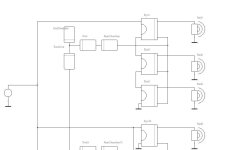
For better understandig, the speaker should look like this:

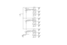
The acoustic circuit maybe like that:

Don't know if it's too weird, but I have this idea of an line array in 3 chambers wich are connected to a transmission line. I try to figure out how to simulate this in hr but I dont get it. The chassis were 9 pcs. dayton pc83-4 in an 3p3s arrangement. The 3 parallel chambers (with 3 chassis in series) should have a port to the tml at 1/4, 1/2 and 3/4. This would normally be a backloaded horn but with an offset of the connected port and on top 3 of them. I found the ME1/2 parameter but I think I need more off a ME2/3/4 instead.
Maybe someone can give me a hint.
Thx!
3emb0t
Edit:
For better understandig, the speaker should look like this:
The acoustic circuit maybe like that:
Last edited:

Hi DonVK,
You're right, I mean the pc83-4 and correct the typo.
Thank you for the circuite. Didn't worked with akabak yet but will give it a try. 😃
You're right, I mean the pc83-4 and correct the typo.
Thank you for the circuite. Didn't worked with akabak yet but will give it a try. 😃
I have a few PC83-8, and it's performance matches the datasheet.
If you want to model arbitrary configurations, Akabak3 is a good way to go. Hornresp can export Akabak2 models that can be nudged into Akabak3. I did not show it, but you can also add filters to the model.
If you want to model arbitrary configurations, Akabak3 is a good way to go. Hornresp can export Akabak2 models that can be nudged into Akabak3. I did not show it, but you can also add filters to the model.
That's good to hear. I have nether a chassis nor the equipment yet to check the parameters for consistency.I have a few PC83-8, and it's performance matches the datasheet.
I think hornresp is quite a good tool but the possibility to model directly the acoustic circuit in akabak is really nice. Tomorrow I will try it out, have just watched some ytubes. 😄
By filter you mean crossovers? The pc83 has a resonance at 80hz and with the tml, so I hope, the 25 ohm impedanz could be optimised so that there is no need for a suction circuit.
Yeah, it's Akabak or another tool. In HR, the best you could do is lump the 9 drivers and 3 chambers to the middle position and that's what you get. Once you do the work, you'll see it's not that complicated.Does nobody really have an idea?
But in the middle position, the harmonic modes would not calculated correctly, or did I miss it? I could simulate each chamber by itself but there is no possibility to combine the results. I will test it 😀
By filter you mean crossovers? The pc83 has a resonance at 80hz and with the tml, so I hope, the 25 ohm impedanz could be optimised so that there is no need for a suction circuit.
Filters of all types (LP, HP, notch, etc). When the drivers are put in series the inductance increases and the system HF attenuates more than a single driver. There is also the baffle step (4Pi to 2Pi transition) to deal with. It's also possible to correct the FR using global EQ for the speaker, like from a PC based EQ'd source. More often than not some type of EQ is required and you can try these schemes within Akabak to get the end response you need.
I'm not sure if it's better with 3p3s or 3s3p. There are other things like the chamber volume that is effected by the configuration. Effective the general impedanz is the same, the hf drop is maybe self correcting. The Vas in series is only 2 litres and with 4.7 litres, the bass reflex resonance is near 80 hz. After simulation, I let the box side open and close it tide with clamps, so that I could change the electrical configuration. Was thinking about a test build with variable parameters, duct position, horn length, etc. Why is there a baffle step from 4 to 2 pi? I thought that's just a physical thing. The actual model ist just 124mm wide with rounded edges and maybe with a valvet fabric on the front to change the step. Step frequency at 124mm is 2.7khz.
The LEM model will not include baffle step, but you can add it easily (1st order accurate) using a BEM PressureBox primitive linked to the LEM radiators. More accurately (2nd order accurate) you need a physical model of the cabinet (with round overs) provided by a STEP file converted to mesh for combined LEM/BEM sim. The baffles step occurs when the radiation space goes from 2Pi (baffle backstops any radiation) to 4Pi space (more freedom, pressure drops). The baffle step (typically -6db) depends on the baffle dimensions, the driver radiator size, and the wavelength.
IMO the 3p3s (shown in post #3 is preferred because the voltage drop is the same on each series branch. However there will still be some variation within the 3 series drivers as their impedance will vary (mfg tolerance) but the current is the same through all series drivers in the branch. The 3s3p will be most sensitive to impedance variation and driver voltage variation. Not sure if you could hear the difference. A MonteCarlo simulator would be needed to see the distribution of outcomes based on expected tolerances.
IMO the 3p3s (shown in post #3 is preferred because the voltage drop is the same on each series branch. However there will still be some variation within the 3 series drivers as their impedance will vary (mfg tolerance) but the current is the same through all series drivers in the branch. The 3s3p will be most sensitive to impedance variation and driver voltage variation. Not sure if you could hear the difference. A MonteCarlo simulator would be needed to see the distribution of outcomes based on expected tolerances.
Good, first I thought you mean there will be a baffle step because the 3s config. Sketchup is a crap, fusion will not run, so I learnd onshape, great tool. The above model was my first onshape output. 😉
Now I have a better model and a step file (not possible with sketchup free) :

Anyway my pc f...ed up when I open akabak, so I was not able to try it out. Anyway, ready for the next try.
Now I have a better model and a step file (not possible with sketchup free) :
Thats exactly the reason I decided 3s per chamber and a chamber at all. The interference between the 3 drivers are at minimal and they act like one. I think there is no need to change the conf afterwards. Hope more, they would not sound like fart. 🙄. At the moment its just an idea, maybe overcombined. For 130 bucks I will get a better chassis but no line array.but the current is the same through all series drivers
Anyway my pc f...ed up when I open akabak, so I was not able to try it out. Anyway, ready for the next try.
OK, akabak running, model implemented, values entered and to much errors 🙂 I try it again tomorrow

OK guys,
after some problems with my pc and a second new laptop Iam back in business.
After building the LEM and some corrections,

I was not able to do the BEM. After a lot of reading I have got it to work:

I split to model in half (at onshape) to reduce the calculation time in akabak (you have to activate symmetry in the parameter tap, I dont finish the solving yet). Here is the BEM:

The solving needs just to long, so I have simplified the bem to just the chassis and a diaphragm as the TML output. To not short the sound I inserted an infinite baffle behind the chassis, set a mic out 1m in the front an run the calc. So I dont have the baffle step diffraction but at least the LEM output. Here is the first output. Unfortunately not as expected:

The TML looks absolutly not linear. The chambers 3 chambers (each 4.7 l) and the TML were optimized at 80 hz, so I was expecting a peak at 80 hz and a -3db drop after 4khz because of a driver distance of 85mm (->f=c/d), but there is just a drop peak. Also I dont know where the massive -6db drop comes after 1 khz. The driver alone runs normaly linear to 15khz:

Thanks for the support and the patience. I look forward to constructive answers.
3mb0t
after some problems with my pc and a second new laptop Iam back in business.
After building the LEM and some corrections,
I was not able to do the BEM. After a lot of reading I have got it to work:
- exported the step file from onshape (newest version)
- load the step in gmsh 4, do a lot of scripting to get just the outer surface as a physic, do a "Mesh 2" an two times a "RefineMesh"
- export the msh in version 2 ASCII and load it in akabak in the general tab, scale it and spec the physic as include
I split to model in half (at onshape) to reduce the calculation time in akabak (you have to activate symmetry in the parameter tap, I dont finish the solving yet). Here is the BEM:
The solving needs just to long, so I have simplified the bem to just the chassis and a diaphragm as the TML output. To not short the sound I inserted an infinite baffle behind the chassis, set a mic out 1m in the front an run the calc. So I dont have the baffle step diffraction but at least the LEM output. Here is the first output. Unfortunately not as expected:
The TML looks absolutly not linear. The chambers 3 chambers (each 4.7 l) and the TML were optimized at 80 hz, so I was expecting a peak at 80 hz and a -3db drop after 4khz because of a driver distance of 85mm (->f=c/d), but there is just a drop peak. Also I dont know where the massive -6db drop comes after 1 khz. The driver alone runs normaly linear to 15khz:
Thanks for the support and the patience. I look forward to constructive answers.
3mb0t
The low frequencies constructively add, the upper frequencies destructively interfere at one meter.Also I dont know where the massive -6db drop comes after 1 khz.
At a distance where the path length to all the drivers is within 1/4 wavelength, they will tweet together!
Rather than using so much cabinet volume on a transmission line with limited low frequency potential, you might think of using a woofer in the space.
One cheap 10" could put out far more low frequency than the nine 3" drivers driven to Xmax, and eliminate the intermodulation distortion the little drivers will have at just 87 dB.
Art
I dont know where the massive -6db drop comes after 1 khz. The driver alone runs normaly linear to 15khz:
it will look like this if you're in the near field of array, which at high frequencies extends for hundreds of meters.
you need to stand about a mile away from the speaker for all the drivers to add in phase at 20 khz.
understand that line arrays at concerts are designed to work at very large distances.
beyond that i have no idea what you're trying to accomplish in the first place.
it's impressive that you were able to simulate whatever that thing is though.
can you explain the purpose of the transmission line ?
and even if this thing worked you would have a different loading for every group of 3 drivers which can hardly be a good design.
finally a good array would extend all the way to the floor that way it is continuous with the floor reflection ...
my advice is forget transmission lines. and if you want to do arrays use drivers with rising response. frankly you will need ribbons for the high end.
if you want to do arrays you will have to read some very technical papers on the subject but when it comes to transmission lines i am afraid there won't be anything you can do to make them perform much better than a bose wave radio. there is simply no good way to combine the rear wave with the front wave. whether it is transmission lines or dipoles people will never stop trying because people like to believe that dreams can come true ...
and they can but only if you move the goal posts by inventing new definitions of what makes a good speaker ...
there are two ways to do this hobby - you can study the science to achieve objective goals ... or you can build whatever you like and then rationalize why whatever result you got is what you wanted ...
you can also simply stop listening to music that doesn't sound good on your speakers and say that it is bad music ...
if that sounds appealing to you then don't give up on Transmission lines.
there is also another approach where you take an alignment that works ( like bass reflex ) and disguise it as transmission line or horn or something that would look fancy in marketing material. then fans of transmission lines or horns will point to your design as proof that their beloved speaker type isn't hopeless.
reality is that all alignments are imaginary. there is only air and boundaries. everything else is in your head.
for example Josh Ricci designed fairly decent bandpass subwoofers and marketed them as horns. because there is no legal definition of what is a horn.
i haven't looked inside Volt speakers but i suspect their "transmission lines" are also something else. and the B&W nautilus "transmission line" is functionally more like a labyrinth.
it's the same as how the Chinese will do a chip amplifier then put one vacuum tube on top that isn't connected to anything and say it's a vacuum tube amp. saddest part is that $10 amp will probably outperform real tube amps costing thousands.
bottom line - before you model something you should be able to explain what you're trying to achieve.
Last edited:
The solving needs just to long, so I have simplified the bem to just the chassis and a diaphragm as the TML output. To not short the sound I inserted an infinite baffle behind the chassis, set a mic out 1m in the front an run the calc. So I dont have the baffle step diffraction but at least the LEM output. Here is the first output. Unfortunately not as expected:
The TML looks absolutly not linear. The chambers 3 chambers (each 4.7 l) and the TML were optimized at 80 hz, so I was expecting a peak at 80 hz and a -3db drop after 4khz because of a driver distance of 85mm (->f=c/d), but there is just a drop peak. Also I dont know where the massive -6db drop comes after 1 khz. The driver alone runs normaly linear to 15khz:
Thanks for the support and the patience. I look forward to constructive answers.
3mb0t
Looks like you've made some progress on the model. There is a much faster way to check the basic design concept. Using BEM pressure boxes will allow positioning the radiators at the correct locations (exterior summing) while using LEM for the drivers and chambers. This allows easy and fast design changes, will solve very quickly, and support experimenting / refining the design before fine detail modelling.
The LEM model will not include baffle step, but you can add it easily (1st order accurate) using a BEM PressureBox primitive linked to the LEM radiators. More accurately (2nd order accurate) you need a physical model of the cabinet (with round overs) provided by a STEP file converted to mesh for combined LEM/BEM sim.
If you provide your Akabak project file (here or in a PM) I'll nudge it into working (PressureBox), then you can experiment with it. BTW if you ask a moderator you can get the thread title changed since its primarily about Akabak modelling.
[edit] All of the internal structures (chambers, line segments, ports, drivers) that are connected will also interact so they cannot be separately designed then connected.
Last edited:
At a distance where the path length to all the drivers is within 1/4 wavelength, they will tweet together!
fc=344/(4*0,085) ~ 1khz that makes sense.
Yes, a bigger chassis makes more pressure, a small one has more dynamic and with an line array, so I thought, is more "room" for the sound (until 1khz 🙂 ).
can you explain the purpose of the transmission line ?
The idea behind the TML was to reduce the impedance peak at fs 80hz of 25 ohm, so maybe no suction circuit is needed and to have less electrical components. A FM300A, a DAC with 2x 8x TDA1543 and you have almost no components from "bit to ear".
In general you are totally right. The purpose of an line array is not to put in your living room. I try to figure out an extrema (smallest baffle, many chassis on the front), almost all speakers from standard (4-5 chassis in the front) to the most expensive high ends are designed like that. Focal , gryphon kodo and all the others with a dozen mids and subs and a tweeter in between. This project shows me, all these speakers will not work without an active crossover dsp.
And by the way, Compensated Transmission Line Array sounds kinda cool. 😎 Never heard before and in a thousand years, all speaker will be like that. Joking aside, it is an experiment.
You re right, I tested it before. The output was weird, so I tried the inf baffle (not really a difference). I was not expecting this outputUsing BEM pressure boxes
Thank you again for your support. Your words (post 11) have such deep meaning, I only understood most of them when I was faced with the problem in Akabak. 😆poor me.
Akabak is a little more complex as Hornresp, the first idea where I started a few day ago. Last time I build speakers is over 25 years ago. Most of them were like Visaton VOX 251 /253 (or other AL170 build). No one was using software like that for private purpose. So its fun to start from the beginning.
By the way the, the drop at 4khz is because of an interference extreme, where the mic is. (p1006 is 5 meters).
The TML at the top of the array has an really bad influence to the pressure output. There is no linearity how the TML output is bending the sound cone down. Over the sweep the pressure cone is wiggling down an back all over from 800hz up to 20khz.
At 9khz, near perfect symmetrical:
At 12khz, the TML is like screaming:
@DonVK, I'll send you a PM with the files as soon as I've put everything together in a few days.
greetings 3mb0t
DonVK had made some tests and send me the model back. He made a BEM with a duct and a baffle. In the baffle, the diaphragms can be added as items. This is the comparison of the frequency responses:

As you can see, baffle step frequency is around 930 hz and the f3 of the baffle step is 440 hz. The db level above 1khz is around +6db. There are some peaks starting from 360hz an then f1=f0*sqrt(2). Dont know from what but I will figure it out. In a vPolar response (1m, 90° up) you can see them better:

As you can see, baffle step frequency is around 930 hz and the f3 of the baffle step is 440 hz. The db level above 1khz is around +6db. There are some peaks starting from 360hz an then f1=f0*sqrt(2). Dont know from what but I will figure it out. In a vPolar response (1m, 90° up) you can see them better:
If you haven't, I think it's worth doing that simplified model in HR (even if you keep it to yourself). It wont help your directivity investigation, but it might aid your pipe sizing. FWIW.
- Home
- Loudspeakers
- Multi-Way
- Compensated transmission line array