Not based on wild guessing though.
Check the phase margin and do standard stability tests.
It can be 68p to 120p for many reasons.
Not gonna write a audio textbook in a post.
120p is my limit since the slew rate is getting murdered regardless at such a high level.
Many other things could be playing into the reason why so much phase is causing such a needed high value
Either way it is a straight forward fun amplifier.
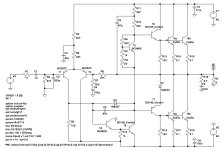
Interesting , missed that one, ill take a look at itMember LKA had this addl' components in one of his bootstraped amp designs, he called it VAS starter. If I read it correctly its duty is to prevent turn on and off thump. I adapted it and run it in sim but I did not verify it in a real world build but perhaps from a lower rail voltage like lineup's it may not be necessary.
Amplifier is certainly stable at 100pFNot based on wild guessing though.
Check the phase margin and do standard stability tests.
It can be 68p to 120p for many reasons.
Not gonna write a audio textbook in a post.
120p is my limit since the slew rate is getting murdered regardless at such a high level.
Many other things could be playing into the reason why so much phase is causing such a needed high value
Either way it is a straight forward fun amplifier.
But I like the AC Sweep curve to be all flat.
You think slewrate is too low at 330pF.
Why we need high slow rate .. is this important?
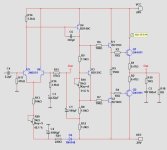
If I wanted to find the better (if not best value of C6) this is how I would do it, verify it in the closed loop plot (bode plot), lowering C6 will definitely increase frequency at -3dB, and the effect may drop gain margin. And of course you will have to find the better balance between phase and gain margin with your chosen value of C6.
if you do your simulation not with TO126 BD 139C then you will get better results...KSC3503 or TTC are faster...
at the real amp you have to measure the real overshoot/or not with square wave.
at the real amp you have to measure the real overshoot/or not with square wave.
Another point of interest in these types of designs - is what happens when you REALLY cheap out on the transistors. Ie, NPN=2N3904, PNP=2N3906, outputs TIP41/2. Or salvaged transistors pulled out of something. The whole idea being able to build a decent little amp without spending ANY money, or get every single part from Radio Shack. I’ve built them before, and managed to get them to sound pretty damned good until the Radio Shack power transformer runs out of juice and then it clips of course. But never simulated or measured distortion.
Best one I had used ring of two CCS’s for the LTP and VAS, which could be tweaked to get good differential balance and maintain it with the wildly varying supply voltage that the cheap RS trafo provided under load…… Yeah, you had to cherry pick the 2N3906’s or 2SA733’s (which were often free, as pulls from old car stereos).
Best one I had used ring of two CCS’s for the LTP and VAS, which could be tweaked to get good differential balance and maintain it with the wildly varying supply voltage that the cheap RS trafo provided under load…… Yeah, you had to cherry pick the 2N3906’s or 2SA733’s (which were often free, as pulls from old car stereos).
I have repaired and listened to something truly retro and was pleasantly surprised. It has singleton input, quasi-complementary topology with output electrolytic. And it is musical! I bought the thing to gift it to a friend, I wasn't expecting it to sound that good and engaging.
Are you sure it will be better?
I can try however and see what happens.
now i want to cut parts from it, im obsessed with dead simple designs mostly becuse of the simpler assembly process.Any questions or comments?
I see The One and Only has LIKED my amp ...
So it can not be so bad then.
The LTP input stage using a resistor instead of CCS have worse PSRR so it needs a cleaner power supply, I think it may be a good idea to therefore isolate the input stage and avoid its power supply being affected by the other stages, including the VAS, it's a small change preserving the simplicity of the amplifier.
You are welcome!now i want to cut parts from it, im obsessed with dead simple designs mostly becuse of the simpler assembly process.
You will be the first to set it up.
Output transistors can be any BJT TO-220 or whatever.
Good luck!
Yes.C6 is 330pF?
It was dimensioned while doing AC Sweep.
Of course it is possible to reduce the value.
But I keep it at 330 pF.
CRD diode at LTP?
It is possible. But having a potentiometer makes it easy to adjust DC-offset on the output.
circuit in post #34 :
In 1979 I build a poweramp using quite the same circuit except its output is quasicomplimentary.
In the real build the LTP is with BC212, outputs BD249C. Could be easily changed to complimentary. with BD249C/250C
Since there is no savety circuitry in the amp itself, it is powered by a stabilized supply with overcurrent protection/shutdown.

.asc-file added below to play with it.
In 1979 I build a poweramp using quite the same circuit except its output is quasicomplimentary.
In the real build the LTP is with BC212, outputs BD249C. Could be easily changed to complimentary. with BD249C/250C
Since there is no savety circuitry in the amp itself, it is powered by a stabilized supply with overcurrent protection/shutdown.

.asc-file added below to play with it.
Attachments
- Home
- Amplifiers
- Solid State
- Basic Power Amplifier Retro

