I loved the bias scheme 2x 😎 general bias (failsafe; if pot opens, the bias goes down) and a balance adjuster. Excellent!
EDIT: But, for more failsafe yet, I made the following for my PP amp with PL 509: the balance pot wiper is directed to ground, and bias is applied with R divier (almost the reverse of the schema). Then, if pot opens, the bias go to minimum.
EDIT: But, for more failsafe yet, I made the following for my PP amp with PL 509: the balance pot wiper is directed to ground, and bias is applied with R divier (almost the reverse of the schema). Then, if pot opens, the bias go to minimum.

Are you sure that the required changes remain mimimal between the venerable (= pre WWII) GU50 and the relatively recent 6P41S? And which OPT is needed?
Best regards!
Best regards!
Hithe entire process of creating and setting up an amplifier is shown without hiding anything
I went trough the topic by link - thanks.
Looks great...
Are you sure that the required changes remain mimimal between the venerable (= pre WWII) GU50 and the relatively recent 6P41S? And which OPT is needed?
Best regards!
you don't have to take it literally.
you need to understand the general logic of tuning
1. selection of output stage tubes by proximity of characteristics
2. soldering the circuit without a printed circuit board (so as not to catch generation or background...)
3. tuning. setting the current of the output tubes - then - balancing by minimum THD on the screen of the spectroanalyzer.
4. fine tuning by adjusting the cathode resistor to the minimum THD at the output of the audio transformer.
the result is stunning.
no need to build 15 triode tubes for the sake of 8 watts at 7% THD
It is much more pleasant to enjoy tube sound without distortion rather than having to rely on triodes for the sake of nothing.
The main thing is understanding of the process of customization, not blindly following the purchase of expensive components for the sake of what is unclear
the key to success is a competent circuit + competent tuning with the help of a spectroanalyzer
the best gain stage in an amplifier is the one that doesn't exist!!!
because this is the only way it (gain stage) does not introduce distortion !🙂)))))
why a 4 or 6 triode driver????
to spoil a beautiful tube GU50 or 6p45s by converting it to triode, while the power will not be 35 watts in Class A - but only 20, and the NER will be 10 times higher.
Isn't this the stupidity of marketing for the sake of selling expensive lamps without clear results?
Hi
I went trough the topic by link - thanks.
Looks great...
an absolutely sure sign of a quality amplifier
"Spouse asks to turn the sound up louder and put on some more songs at 1am🙂)))"
check out these speakers
Last edited:
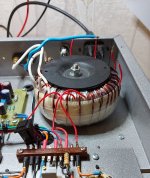
Thank you. What is the plate-to-plate primary impedance of the output transformer?output audio transformer - TOroidal - with an overall power of 80 or more Watts
Thank you. What is the plate-to-plate primary impedance of the output transformer?
Output transformer
Raa=5kOhm
Rn= 4Ohm, 8Ohm
overall power 80W
- 1300-0-1300 (0.28mm)
- 0-74-104 (1.3mm)
TOR dimensions 92x45mm
precise matching of the amplifier with the load - by selecting the power supply value of the second grid - this is looked at on the Spectrum Analyzer at a minimum of TND
when the optimal value in volts is found, it is tedious to extinguish the excess voltage not with a resistor, but with a zener diode connected in series
sometimes this helps reduce the TND several times
https://www.nadotornado.com.ua/foru...mpyuternogo-kompleksa-shmeleva-obzornyj-rolik
https://www.nadotornado.com.ua/foru...shtuvannya-lampovogo-pidsilyuvacha-1-na-6p41s
///...UL inclusion does not mean that it will sound better. If you make UL inclusion, you need more swing from the FI, increase the swing, you get more NIR from the preamp and the FI and in the end the sound is worse. Transfer to triode inclusion, even dumber output stage becomes, even more boost is needed, NIR after FI increases 10 times compared to pentode inclusion, output power decreases three times and in the end it turns out to be not HI-FI but a radio on a pole of 1930s....///
Are you sure that the required changes remain mimimal between the venerable (= pre WWII) GU50 and the relatively recent 6P41S? And which OPT is needed?
please clarify the question in more primitive words - translation difficulties
=================
roughly speaking - the circuit is the same - the differences are only in the type of the electron tube used, and in the supply voltages and current
for example
GU50
anode - 630 volts - current 60 mA - the circuit is the same - but this is for a loud party - and not for sound quality
for quality - only Class A
for example - the same audio transformer that worked at 630 volts and 60 mA - it will be able to work at 400 volts anode and 95-100 mA
And this is Class A
then you can connect 4 Ohm speakers to the 8 Ohm terminals
audio transformers should be of high quality
but that doesn't mean it makes sense to pay more than half the price for a big name
Who can guess what the top layer of the secondary winding with bare wires is for?
Attachments
Last edited:
Absolutely 😎an absolutely sure sign of a quality amplifier
"Spouse asks to turn the sound up louder and put on some more songs at 1am🙂)))"
What are the impedances of the output transformers in those examples? In the last one is it 1300 + 1300 = 2.6k Raa?
Hi all
Svytoslav,
Your diagram show for 2x 6P36C in PushPull mode : 2600 tr/ 66 tr for 4Ohm If my calculations are correct : 6KOhm
I'm very intrigued, I'm using only 3,5KOhm for PP, exactly 850Ohm for a circlotron circuit (Zaa divided by 4)
HT anode and HTG2 are the same : 360V and 160V
Yan
Svytoslav,
Your diagram show for 2x 6P36C in PushPull mode : 2600 tr/ 66 tr for 4Ohm If my calculations are correct : 6KOhm
I'm very intrigued, I'm using only 3,5KOhm for PP, exactly 850Ohm for a circlotron circuit (Zaa divided by 4)
HT anode and HTG2 are the same : 360V and 160V
Yan
It's even (2600/65)² * 4 = 6400 [Ω], and the tubes are even 6P45S's, if I read that correctly. Strange, indeed, and no way with 35 W output power with 390 V plate voltage...
Best regards!
Best regards!
Those 65 turn windings would have to go in series to get that kind of power (1600 ohm Ra-a). Sweep tubes with high peak anode currents approaching an amp can support that. It’s a little out of KT88 territory.
No doubt about that. But 390 Vdc and 6400 Ω plate to plate load, as named in the schematics, would make 35 watts of output power impossible.
Best regards!
Best regards!
Perhaps the schematic is simply incorrect. The tubes can do it (more or less) with the proper impedance.
I'm even using lower plate-to-plate impedance (a little less than 3k5) with 340V +B and with only 105V for Vg2, and got some >50W, not all in class A, of course. Low +B and Vg2 ensures safe large dissipation for large class A part... 10 years and counting, not all this time operating/on of course ;-) operating each PL509 with continuous 32W on anodes. Safe from red plating.
- Home
- Amplifiers
- Tubes / Valves
- Those Magnificent Television Tubes