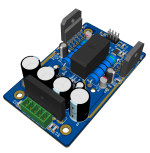
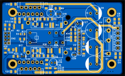
Here's my on-going Mini LM3886 Stereo Project. using SMT 1206 for easy DIY assembly and reduced PCB size.
The design includes, Power Supply rectifier and Speaker Protection. Preamp will be added later.
I am assembling the prototype then testing, Gerber will be available open source.
The design includes, Power Supply rectifier and Speaker Protection. Preamp will be added later.
I am assembling the prototype then testing, Gerber will be available open source.
Attachments
Last edited:

Nice!
But you need a 20k resistor from Audio-IN to ground.
Or else you will get DC-offset on the output.
But you need a 20k resistor from Audio-IN to ground.
Or else you will get DC-offset on the output.
Thanks for the feedback, I will be adding Bluetooth module, Pre-amp and DC blocking capacitor. on top of the relay.
Nice!
But you need a 20k resistor from Audio-IN to ground.
Or else you will get DC-offset on the output.
How are you planning to attach the heat sinks?
Also, you don't have enough decoupling by the LM3886 to ensure stable operation with a 4 Ω load. Here're my recommendations: https://neurochrome.com/pages/supply-decoupling
I also recommend that you consult the Application Section of the LM3886 data sheet on this topic.
Tom
Also, you don't have enough decoupling by the LM3886 to ensure stable operation with a 4 Ω load. Here're my recommendations: https://neurochrome.com/pages/supply-decoupling
I also recommend that you consult the Application Section of the LM3886 data sheet on this topic.
Tom
How are you planning to attach the heat sinks?
Also, you don't have enough decoupling by the LM3886 to ensure stable operation with a 4 Ω load. Here're my recommendations: https://neurochrome.com/pages/supply-decoupling
I also recommend that you consult the Application Section of the LM3886 data sheet on this topic.
Tom
Thanks, for the feedback.
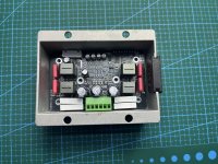
I will use the same enclosure/Heatsink from my another project.
I have multiple 0.1uF , 2.2uF Decoupling Caps, I will check the performance at 4 Ω and add more as needed during the prototype Testing.
Attachments
Last edited:
I see the decoupling capacitors in the schematic.I have multiple 0.1uF , 2.2uF Decoupling Caps, I will check the performance at 4 Ω and add more as needed during the prototype Testing.
National Semiconductor (now TI) recommends: 100 nF || 10 uF by the IC and a minimum of 470 uF of bulk capacitance on the board. See the Application Section of the LM3886 data sheet. I have seen the LM3886 oscillate with a 4 Ω load if the 10 uF is missing or reduced below 10 uF.
I take it a step further in my recommendations which you can read in the link I provided in Post #4.
I doubt you'll get much heat sinking out of that chassis. It looks like it was intended for a Class D amp. They develop considerably less heat. Anyway. You'll find out soon enough.
Tom
Ok Noted, Thanks. my PCB design have multiple locations for me to replace the decoupling capacitors to higher values if needed without adding a new component.National Semiconductor (now TI) recommends: 100 nF || 10 uF by the IC and a minimum of 470 uF of bulk capacitance on the board. See the Application Section of the LM3886 data sheet. I have seen the LM3886 oscillate with a 4 Ω load if the 10 uF is missing or reduced below 10 uF.
I take it a step further in my recommendations which you can read in the link I provided in Post #4.
My application use case will only be 8Ω Stereo 30-50W Power range, worst case performance validation only for 4Ω.
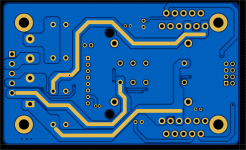
The PCB grounding plane and short routing will reduce the impedance in power path. Exposed copper provision to further reduce the impedance if needed.
For the enclosure, It's just a Mini Amp, I will just test how much power the aluminum enclosure can handle, it look small, but the bottom side is very thick.
Last edited:
@tomchr has been developing and selling 3886-based amps succesfully for years.
You would be smart to take his recommendations serious.
Jan
You would be smart to take his recommendations serious.
Jan
I'm taking it seriously, I've been designing for power supply and PCB for years too, each new PCB design will have their own electrical characteristics, and performance need to be adjusted depending on the parasitic elements, other LM3886 works well, others not with same components but different PCB . as a DIY or Engineer , we need to Listen, Learn and explore.
.... wreck your speakers in the process.we need to Listen, Learn and explore
If the LM3886 decides to oscillate with your speakers connected you can assume that your tweeters will go bye-bye. I'm just trying to prevent you from having that ... "learning experience".
Tom
First rule in DIY amplifier, If you are testing amplifier prototypes, you should not be using an actual speaker. test it with load simulator, You should conduct normal parameter test procedure then proceed with worst case testing parameters, this way you will gradually understand the performance of your design.
experimenting on decoupling capacitors values is just part of design and debugging process, . My goal is understand the real root cause of the LM3886 oscillation, since it's a very common issue, I've seen very simple design that works , some following all design recommendation but not working properly. I want to see and understand , experience the problem.
experimenting on decoupling capacitors values is just part of design and debugging process, . My goal is understand the real root cause of the LM3886 oscillation, since it's a very common issue, I've seen very simple design that works , some following all design recommendation but not working properly. I want to see and understand , experience the problem.
I would argue that the first rule in a DIY amplifier build should be: Read the data sheet.
In case of the LM3886, you can find National/TI's recommendations for the decoupling on page 20 of the LM3886 data sheet. They're in the section titled "Supply Bypassing".
Tom
In case of the LM3886, you can find National/TI's recommendations for the decoupling on page 20 of the LM3886 data sheet. They're in the section titled "Supply Bypassing".
Tom
That recommendation is valid and I thankfully noted, but it's not 100% with all PCB design. I've seen products using that values have issues, most product in the Market uses that same components values , but if you search the Net. you can find tons of same LM3886 issues.
My PCB design have all that components place and it's just a matter of replacing the values, all relevant provisions are there to experiment, without changing the designs. But after researching, component recommendations also not performing well enough.
My PCB design have all that components place and it's just a matter of replacing the values, all relevant provisions are there to experiment, without changing the designs. But after researching, component recommendations also not performing well enough.
In the datasheet the Decoupling capacitor is not the critical components to manage the Oscilation. RsN, CsN, L and Bulk Capacitor values determine the oscillation.
4 Ohms load will cause higher current draw from the power supply, and High Current sink to the load, this will expose the parasitic impedance of the PCB design, the variation in signal Freq, Surge Current Demand will cause voltage drop in the Power Path, this will create a ripple in the DC Bus, t the Drop in DC Bus voltage will cause a feedback gain compensation from the amplifier, but will be unable to compensate, and will generate oscillation or clipping or distortion. The L will try to resist the sudden increase in Load current and the RsN and CsN will generate a snubbing function or pre-loading at the output if load suddenly reduce.

4 Ohms load will cause higher current draw from the power supply, and High Current sink to the load, this will expose the parasitic impedance of the PCB design, the variation in signal Freq, Surge Current Demand will cause voltage drop in the Power Path, this will create a ripple in the DC Bus, t the Drop in DC Bus voltage will cause a feedback gain compensation from the amplifier, but will be unable to compensate, and will generate oscillation or clipping or distortion. The L will try to resist the sudden increase in Load current and the RsN and CsN will generate a snubbing function or pre-loading at the output if load suddenly reduce.
Last edited:
I didn't said you are wrong, I said that components suggestions doesn't work with many of the design. If all that is right, many designs should have no problem. But search in the Net Tons & Tons of LM3886, oscillations issues with that component recommendations. . and that's I want to find out.
It's better for me to check the water first before I drink it.I've led you to water. It's your choice whether to drink.
I didn't said you are wrong, I said that components suggestions doesn't work with many of the design. If all that is right, many designs should have no problem. But search in the Net Tons & Tons of LM3886, oscillations issues with that component recommendations. . and that's I want to find out.
I think you got it wrong, just because your lm3886 amp will include those recommended decoupling caps that doesn’t equal oscillations free amplifier, but not using the recommended decoupling caps will most likely trigger the oscillations .
- Home
- Amplifiers
- Chip Amps
- Mini LM3886 Stereo Project