Hi Guys,
I'm desperately trying to get my first valve pre to work with my TDA dac based cd player and again I have ran into issues with what seems like 120hz noise.
I had help with getting the bias resistor correct (lAMPIZATOR DESIGN) and I tested the pre and was kinda happy but when you turn it up there is a very loud buzzing when the volume is increased.
This is my orignal thread about bias resistors:
I have the exact same kit as the person in this thread and he also talks about buzz, its all I have to go on. This pre uses high voltage and I rather not guess anything. Any help is greatly appreciated:
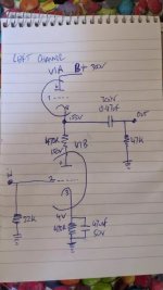
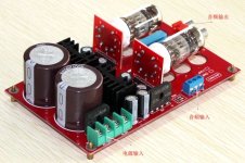
Please note the pin 9 is floating. My ac is 220v and directly across the smoothing cap is 288V DC. I have used the 240v mains input and used the 2 6.3V to heat the tube (not using the centre tap) (they are actually 3.15v each) My filament voltage is 6v.
The sound is great at low volume but when I turn my amplifier up there is a loud buzz. I used an app and around 120hz is spiking, its fast and loud.
I also tried bypassing the 2 smoothing caps with 0.1uf 400v and it didnt make any difference. Thanks
I'm desperately trying to get my first valve pre to work with my TDA dac based cd player and again I have ran into issues with what seems like 120hz noise.
I had help with getting the bias resistor correct (lAMPIZATOR DESIGN) and I tested the pre and was kinda happy but when you turn it up there is a very loud buzzing when the volume is increased.
This is my orignal thread about bias resistors:
Hi guys,
I am a complete valve noobie. I've always wanted to convert one of my TDA1541 cd players to valve output like Lampizator does.
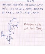
The stock kit I 've had for a while has 470r resistors for the cathode but lampizator recommends 150r. The service manual for 6N2 states 2.25 +- 0.45MA
I read a forum that I copied the cicruit diagram from but doesnt mention anything about the resistor. Its the exact same circuit as mine. In that forum is not being used as I/V
This link below from lampizator states for 6n2p use 150r. "150-250 Ohms for 6H2P". I have also attached the document...
I am a complete valve noobie. I've always wanted to convert one of my TDA1541 cd players to valve output like Lampizator does.
The stock kit I 've had for a while has 470r resistors for the cathode but lampizator recommends 150r. The service manual for 6N2 states 2.25 +- 0.45MA
I read a forum that I copied the cicruit diagram from but doesnt mention anything about the resistor. Its the exact same circuit as mine. In that forum is not being used as I/V
This link below from lampizator states for 6n2p use 150r. "150-250 Ohms for 6H2P". I have also attached the document...
- dj_holmes
- Replies: 4
- Forum: Tubes / Valves
I have the exact same kit as the person in this thread and he also talks about buzz, its all I have to go on. This pre uses high voltage and I rather not guess anything. Any help is greatly appreciated:
I have tube pre kit which (supposedly) works with any of these. Which is most linear? Most musical? Or otherwise preffered?
I can get some or all, and compare, but even different supliers can result in different sound.
Any recommendation? They do have different heater current demands, so i have to account for this.
I already have one working in box and second is up and running on the floor. I want to replace all my solid state pre, as this pre has more musicality for me. I got no schematics, sorry.
- adason
- Replies: 109
- Forum: Tubes / Valves
Please note the pin 9 is floating. My ac is 220v and directly across the smoothing cap is 288V DC. I have used the 240v mains input and used the 2 6.3V to heat the tube (not using the centre tap) (they are actually 3.15v each) My filament voltage is 6v.
The sound is great at low volume but when I turn my amplifier up there is a loud buzz. I used an app and around 120hz is spiking, its fast and loud.
I also tried bypassing the 2 smoothing caps with 0.1uf 400v and it didnt make any difference. Thanks
Attachments

I am confused by your pseudo schematic. What is the 90r to gnd? How's the plate loaded? Is the filament grounded? Where is the transformer placed.
Having 150 vs 470 ohms for bias is a huge change. Are you sure your bias is setup right?
You 'seem' to have plenty of filtering at least. Can you get a real schematic?
Having 150 vs 470 ohms for bias is a huge change. Are you sure your bias is setup right?
You 'seem' to have plenty of filtering at least. Can you get a real schematic?
Hi, its 90r to ground and signal goes in there. the transformer is attached separatelyaway from everything. Its in testing so its not even mounted
Ditch that tube and use a 6sn7 or ecc88 and use aikido design.
I built the lampizator and Broskie had a way better design for the voltage out dac. I can't see the problem with akm49.. chips vs tda1541, though the Tda is very seductive I have everything I want from the cirrus.
I built the lampizator and Broskie had a way better design for the voltage out dac. I can't see the problem with akm49.. chips vs tda1541, though the Tda is very seductive I have everything I want from the cirrus.
Thanks for ths suggestion but I quite like the sound. In the other post the person uses crcrc to reduce the noise. I read its about the mains filter being poor, if I can buy a kit to fix it would be great. Otherwise I do have to do it myself with some advice. Or maybe there is something obvious thats wrong? I just don't know
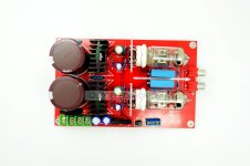
Nice little thing! If you want to improve in audio you need to have some sort of testing equipment.
Hearing can be misleading sometimes and we think we are in the right path but we just amplify the echo of the voice we are tracking as we go astray.
Be careful with a pcb it is easy to make a mistake and damage the traces, it is not fun after that.
Hearing can be misleading sometimes and we think we are in the right path but we just amplify the echo of the voice we are tracking as we go astray.
Be careful with a pcb it is easy to make a mistake and damage the traces, it is not fun after that.
Try this:
Connect the Center Tap of the heater transformer windings to ground.
Increase the bypass cap across the cathode resistor to 470 ... 1000uF.
47uF was low already for 470 ohm, more so with 150 ohm.
Improves PSR ( Power Supply Noise Rejection.)
Connect the Center Tap of the heater transformer windings to ground.
Increase the bypass cap across the cathode resistor to 470 ... 1000uF.
47uF was low already for 470 ohm, more so with 150 ohm.
Improves PSR ( Power Supply Noise Rejection.)
Hi, I will try the centre tap to ground and measure the voltage without the 220V first. If all ok I will connect the high voltage and see.
I have removed the cathode resistor compeletetly. As per Lampizator design and in the thread I posted in my first msg someone wrote:
"1) Since this is a pre get rid of that 47uF cap. Distortion will be lower."
Since I don't know how to measure the distortion I just followed the guide and removed the capacitor.
Also see Lampizator design he didnt put capacitor in cathode
Attachments
What the capacitor does is prevents feedback in the audio range from the cathode potential.
There is no reason to use them.
R2 acts like some antenna because it is a voltage divider, I can't remember why, this is a crucial part of the thing.
My solution was to remove all the gain of the lampizator and just use a cathode follower.
Transform the tube into cathode followers and connect the C1 on the other R1 resistor, should give you a clean signal , not a 10Vrms ... which you don't need.
You can change that to a white cathode follower, but the best would be some design which removes common noise.
How are your dac outputs connected? do you use tda1541?
How are your dac outputs connected? do you use tda1541?
OK the sound level has now drastically increased and I really have to turn it loud to hear the 120hz buzz. Yes I have a TDA1541 cd player. I removed all opamps and connected directly to chip as per Lampizator
In this thread:
The guy added more capacitors with resistors to apparently lower the noise. Any idea how I can do that? What is CRCRC and how do you work out the resistors and wattage?
I have tube pre kit which (supposedly) works with any of these. Which is most linear? Most musical? Or otherwise preffered?
I can get some or all, and compare, but even different supliers can result in different sound.
Any recommendation? They do have different heater current demands, so i have to account for this.
I already have one working in box and second is up and running on the floor. I want to replace all my solid state pre, as this pre has more musicality for me. I got no schematics, sorry.
I can get some or all, and compare, but even different supliers can result in different sound.
Any recommendation? They do have different heater current demands, so i have to account for this.
I already have one working in box and second is up and running on the floor. I want to replace all my solid state pre, as this pre has more musicality for me. I got no schematics, sorry.
- adason
- Replies: 109
- Forum: Tubes / Valves
The guy added more capacitors with resistors to apparently lower the noise. Any idea how I can do that? What is CRCRC and how do you work out the resistors and wattage?
I need the gain as the output is so low. Its difficult to move the components around on this kit.What the capacitor does is prevents feedback in the audio range from the cathode potential.
There is no reason to use them.
R2 acts like some antenna because it is a voltage divider, I can't remember why, this is a crucial part of the thing.
My solution was to remove all the gain of the lampizator and just use a cathode follower.
Transform the tube into cathode followers and connect the C1 on the other R1 resistor, should give you a clean signal , not a 10Vrms ... which you don't need.
I'm now very happy just to remove a tiny bit more noise
Pwer in Watts = Resistor value x Current
C = capacitor
R= Resistor
the Resistor will drop the voltage, so calculate so that you don't lose more than 15Volts, just RCRC is enough. Use big values of Capacitor.
C = capacitor
R= Resistor
the Resistor will drop the voltage, so calculate so that you don't lose more than 15Volts, just RCRC is enough. Use big values of Capacitor.
CRCRC is cap-resistor-cap-res-cap in the power supply filter. If you could use an inductor to replace first resistor or even both and have cLcLc you would get even better filtering.What is CRCRC and how do you work out the resistors and wattage?
- Home
- Amplifiers
- Tubes / Valves
- 120Hz 6N2 Valve pre