I don't fully understand this, but I'm sure you got it figured out. What we commonly know about bass reflex is that at the tuning frequency the driver moves only minimal amount and the air in the port moves a lot and produces sound. The air acts as a membrane.No, the "reflex effect" is the slug of air contained in the port moving in phase with the driver around the box Helmholtz resonance frequency (Fb), the resulting waves travel at the speed of sound.
The "windy" air pressure waves created when the slug of air spills out of the port travel at a small fraction of the speed of sound, and won't be in phase with the driver or port output past a few centimeters.
Out of phase output reduces "kick".
One more video:
It's worth repeating here the rarely mentioned condition known as 'port rectification' which results in the driver's neutral position moving away from its rest position due to asymmetric airflow, eating up cone excursion and introducing distortion as it is made to exceed Xmax in one direction only as the net pressure in the enclosure increases or decreases with respect to the surrounding atmospheric pressure.The port certainly can blow 1-2m into distance, but it does not suck the air in in the same way. Sucking is omnidirectional.
Port 'flow' conditions should be made as similar as possible at both ends to obviate this effect when driven hard.
Last edited:
This is the main reason that small ports are a bad idea - it's like asking a tiny driver to reproduce deep, loud bass requiring excessive excursion.air in the port moves a lot and produces sound. The air acts as a membrane.
If I have to build a ported enclosure, I start with a port with an area equal to Sd and compromise from that point to where it actually fits in the box!
I've only ever once managed to attain this equality with a 10" Peerless driver!
My mantra for good bass - Move a lot of air, GENTLY - applies as equally to ports as it does to drivers.
I've heard more than a few large PA systems that sound like this - all messed up in the time domain!😂 Well that would be a looong delay kick. In music, it kicks on beat. Can't imagine waiting for the beat 10 seconds.
@MrKlinky :
Yes, I know about that one. It depends how bad the design is, because certain aspects and happenstances cause it to be not that big of a problem:
At high frequencies, cone movement is rather small.
At medium low frequencies, the port is not fully kicking in yet, so there is less non-linearity than what would be likely to cause serious problem.
At tuning frequency, the cone movement is small, so cone offset is not so big of a problem as long as someone did not MAJORLY eff up.
At lowest frequencies this can become a problem, more so with high excursion demands on the driver, because it itself often is way less linear when run at or past Xmax as it happens. So the port is not alone in the mess. But yes, can happen, should be dealt with. Modern PA drivers are made with DC offset in mind.
..............
no, the frequencies that move the magazines are most probably not these same as the tuning frequency. That´s not how it works. I would bet that this shows some frequency between port being utilized and being unloaded. I believe that the highest amount of most violent air movements are achieved under port tuning - tried that myself. The driver shows enough displacement to behave like a blower-funnel with these small ports.
'port rectification' which results in the driver's neutral position moving away from its rest position due to asymmetric airflow,
Yes, I know about that one. It depends how bad the design is, because certain aspects and happenstances cause it to be not that big of a problem:
At high frequencies, cone movement is rather small.
At medium low frequencies, the port is not fully kicking in yet, so there is less non-linearity than what would be likely to cause serious problem.
At tuning frequency, the cone movement is small, so cone offset is not so big of a problem as long as someone did not MAJORLY eff up.
At lowest frequencies this can become a problem, more so with high excursion demands on the driver, because it itself often is way less linear when run at or past Xmax as it happens. So the port is not alone in the mess. But yes, can happen, should be dealt with. Modern PA drivers are made with DC offset in mind.
Yes, great general approach, or a starting point. Sadly, the SPL density drops by then, and so people are more likely to make sacrifices.If I have to build a ported enclosure, I start with a port with an area equal to Sd and compromise from that point to where it actually fits in the box!
I've only ever once managed to attain this equality with a 10" Peerless driver!
If ever possible! You know how that goes. Portability, visibility, convenience, logistics, all of these are asking for smaller solutions. So compromise needs to be found still. Otherwise I would not touch anything smaller than 21" ever. :-DMy mantra for good bass - Move a lot of air, GENTLY - applies as equally to ports as it does to drivers.
..............
There goes the "dissonance". Here you convinced yourself into what you wanted.As you can see from the video, the magazines move only at specific frequencies, which should be the tuning frequency of that sub.
no, the frequencies that move the magazines are most probably not these same as the tuning frequency. That´s not how it works. I would bet that this shows some frequency between port being utilized and being unloaded. I believe that the highest amount of most violent air movements are achieved under port tuning - tried that myself. The driver shows enough displacement to behave like a blower-funnel with these small ports.
Thanks Art,My view merely disagreed with your statement that "transient response = frequency response" is a "fact".
No disagreement, the hardware and software used determine how you measure the frequency response and/or transient response.
Right, two speakers can have identical (equal) frequency response, but far different (unequal) transient response to an impulsive signal.
A subwoofer that takes more time to react to an impulse, and rings long after, won't have the same "kick" as one that has better transient response.
Keep up the good work!
Art
The first time I heard the claim that transient response = frequency response was in a Meyer article or blog post. Pretty sure it was either JM or 6o6.
I've held on to that idea and it has served me well...but that's just me, huh?
By two speakers having equal frequency response but sounding different, I didn't mean in terms of them having different acoustic impulse/transient response.
Because by equal frequency response, I meant equal mag and equal phase, which we know gives equal impulse response too.
So I mean to be saying I hear a sound difference in two speakers that appear to have the same transfer functions and same impulses.
The particular FIR filter, or a FIR filter in combination with IIR preconditioning...which both give the same transfer & impulse,.... seem to be the cause of the sonic difference.
It's like an acoustic transfer function can't capture how clean or not clean, the electrical filter is used to produce the acoustic results.
Anyway, my tuning comments have too particular for the main focus of this thread, kick science.
Back to kick science.... I do strongly believe that a strong kick, despite being a particular transient signal, will be best from excellent full-range tuning.
That tuning, and full-range SPL/excursion capability that includes unclipped uncompressed headroom for the transients.
Yes, it's your (mis)interpretation of Bob McCarthy's (6o6) writing about two different, but related parts of measurement.The first time I heard the claim that transient response = frequency response was in a Meyer article or blog post. Pretty sure it was either JM or 6o6.
I've held on to that idea and it has served me well...but that's just me, huh?
We disagree, I know two equal frequency responses may also have quite different phase and transient response, therefore I also know that transient response does not = frequency response.Because by equal frequency response, I meant equal mag and equal phase, which we know gives equal impulse response too.
I agree with Bob:
https://bobmccarthy.com/tag/impulse-response/
"What is the best way to phase align our subwoofers to the mains? There is a hint in the way the question was phrased. I didn’t say time align (and it is not because I am afraid of copyright police). I say phase align because that is precisely what we will do. Simply put, you can’t time align a subwoofer to the mains. Why? because your subwoofers are stretched over time – the highest frequencies in your subwoofer can easily be 10-20 ms ahead of the lowest frequencies. Whatever delay time you choose leaves you with a pair of unsettling realities: (a) you are only aligning the timing for a limited ( I repeat LIMITED) frequency range, and (b) you are only aligning the timing for a limited ( I repeat LIMITED) geographical range of the room. So the first thing we need to come to grips is with is the fact that our solution is by no means a global one. There are two decisions to make: what frequency range do we want to optimize for this limited partnership and at what location.Did I mention that all speakers (as currently known to me) are time stretched? So this means something pretty important. The simplistic single number derived from an impulse response can not be used to describe ANY speaker known (to me) especially a subwoofer...So once again we are back to the same place. If you are going to use the impulse response alone (I say you because it will not be me) to align speakers in different freq ranges you are prone to computational items that will affect the HF and LF sides of the equation differently....It is possible that the value for the impulse will give the correct reading so that the Xover is actually in phase – possible – not probable – but we won’t know until we measure the phase – which is the whole point of this exercise.
Simply put: why bother with a step-saving solution ( Xover alignment by IR) if it is so prone to error that you have to do the second step (Xover alignment by phase) any way? If a step is to be skipped it is the IR – not the phase.
Repeatable, reliable alignment at XOVER where the elements constructively ADD together, comes from the phase response, period. If you like to use the impulse to ballpark it in so that it is EASIER to see the phase response then go for it.
6o6"
At any rate, I have no quarrel with what Bob McCarthy has written about the relationship between impulse, phase and frequency response.
Art
Inductance is the primary contributor to a sub's impulse response, and almost always gets completely overlooked. A sub with lower inductance (Le/Re ratio) will have better impulse response and time domain performance than another sub with higher inductance even if the FR is the same. Higher bandwidth is just a natural byproduct of a low inductance subwoofer.Surely this suggests that it is being used outside it's (low passed) capabilities.
If we take two drivers, one flat to 200Hz, the other flat to 1000Hz and low pass steeply at, say 80Hz, why should the speaker with a higher bandwidth react differently to an impulse?
If you are considering an unfiltered signal, then I agree, but that's not quite the real world...
I also absolutely agree that any driver or enclosure which rings long after the signal has ceased will necessarily blur signals in the time domain. To my ear and in my experience, 'tight bass' (Sorry to use that term, couldn't think of an alternative!) can be correlated to low energy storage in the subwoofer.
But the typical subwoofer gets a low-pass filter somewhere in the bass range, which virtually eliminates/overrides the effect of high voice coil inductance on the impulse response, by slowing the response even (much) more than the inductance. So in the end, for a subwoofer, the frequency response which is slows down the impulse response. So for example a high-inductance subwoofer with an acoustical 24 dB/octave low-pass response (typical scenario) have the same impulse response as a low-inductance subwoofer with an identical 24 dB/octave low-pass response if their low-end frequency response is the same.A sub with lower inductance (Le/Re ratio) will have better impulse response and time domain performance than another sub with higher inductance even if the FR is the same. Higher bandwidth is just a natural byproduct of a low inductance subwoofer.
That's the theoretical point of view which is more or less true, but a real world loudspeaker is not just a theoretical (and/or linear) device.
Last edited:
In short, it's not the inductance itself that is the speed limiter, but the frequency response it causes. But a typical low-pass filter of a subwoofer will cut higher frequencies more, so that will be the determining factor in terms of impulse response, not the speaker inductance.
Not true at all, you are thinking about the inductive rise after Zmin. Inductance is the resistance to a change in current, which is directly related to the time domain. Two identical subwoofers, one with low inductance and one with high, both crossed over equally, the lower inductance one will have better impulse response in their passband. I have quantified and confirmed this many times with klippel measurements on low inductance subwoofers that I have developed. Frequency response and group delay are just a result of the Q of the driver in its alignment, not a cause that affects time domain performance. This is also evident in low inductance subwoofers when you look at IMD or multi-tone distortion, as a subwoofer with better time domain/impulse response performance will naturally have better IMD performance.But the typical subwoofer gets a low-pass filter somewhere in the bass range, which virtually eliminates/overrides the effect of high voice coil inductance on the impulse response, by slowing the response even (much) more than the inductance. So in the end, for a subwoofer, the frequency response which is slows down the impulse response. So for example a high-inductance subwoofer with an acoustical 24 dB/octave low-pass response (typical scenario) have the same impulse response as a low-inductance subwoofer with an identical 24 dB/octave low-pass response if their low-end frequency response is the same.
That's the theoretical point of view which is more or less true, but a real world loudspeaker is not just a theoretical (and/or linear) device.
Here is a good article about inductance - https://adireaudio.com/wp-content/uploads/2018/12/Adire-Audio-Woofer-Speed-by-Dan-Wiggins.pdf
This, many times posted "Woofer Speed" paper only shows that the higher the inductance the more the high frequency tilt (as we can see on the graphs) is hence slower impulse response, nothing more.
Am I missing something?
Can you show measurements of two (sub)woofers with identical frequency responses but different inductances that they have different impulse responses? More precisely the higher inductance one have a slower impulse response despite their identical frequency responses?
Am I missing something?
Can you show measurements of two (sub)woofers with identical frequency responses but different inductances that they have different impulse responses? More precisely the higher inductance one have a slower impulse response despite their identical frequency responses?
Yes, that's why inductance causes high-frequency response tilt (by increases impadance towards higher frequencies in the electrical domain), hence slowing down the impulse response. But low frequencies are inherently slow in current change, so inductance is less effective on them.Inductance is the resistance to a change in current, which is directly related to the time domain.
So all this woofer speed is related to frequency response.
Change my mind (possibly with measurements)!
Last edited:
Yes, a basic understanding of inductance and capacitance in AC circuits. Inductance and its relation to time domain is not exclusive to subwoofers or speakers, it is a variable in all AC circuits. If you google "ELI the ICE man", it will shed some light on how inductance affects an AC circuit.Am I missing something?
If you are going to enter a debate and present a theoretical case about basic AC circuit operation in regards to inductance, it would help to at least be familiar with the concepts that govern it.
But we only want the part, how it affects a loudspeaker.Yes, a basic understanding of inductance
So is there a measurement of two subwoofers with identical frequency responses but different inductances that shows slower impulse response for the higher inductance woofer?
The effects are the same for all RL and RC circuits, which includes speakers.
Yes, I have plenty of measurement data. But I'm not going to drive to work at 4:22 am and invest time into cultivating some data explicitly for some person on a forum without a basic understanding of AC circuits who is trying to argue against commonly learned principles.
https://en.wikipedia.org/wiki/RL_circuit#Impulse_response
https://en.wikipedia.org/wiki/RL_circuit#Time_domain_considerations
https://www.keysight.com/used/us/en/knowledge/formulas/time-constant-formula
In an RL circuit, it measures the amount of energy the inductor can store in its magnetic field. It is a measure of how much a conductor opposes a change in current. A higher inductance leads to a longer time constant, slowing the rise and fall of current.
So you say that two woofers with identical frequency responses but different inductances shows slower impulse response for the higher inductance woofer?
I would like to see that!
I would like to see that!
Hi,
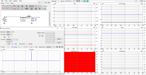
Ideal point source with 20-20k frequency response, 8ohm constant impedance, no inductance whatsoever.
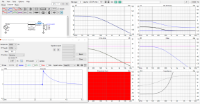
If I put an inductor in series, inductance goes up, frequency response gets low pass, and impulse response changes.
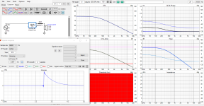
If I replace the inductor with equivalent DSP transfer function, the response is identical and inductance back to 0.
Here linear phase filter for completess.
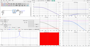
Here DSP cancels low pass of the inductor.
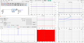
Looking at impulse and frequency responses of these examples, inductance affects frequency response. Impulse is fast when frequency response contains high frequencies. So, inductance = speed if you do not equalize the acoustic response. When acoustic response is equalized, speed is same no matter the inductance was 0 or x. Assuming speed is frequency response and not some magic property not present in these graphs.
Ideal point source with 20-20k frequency response, 8ohm constant impedance, no inductance whatsoever.

If I put an inductor in series, inductance goes up, frequency response gets low pass, and impulse response changes.

If I replace the inductor with equivalent DSP transfer function, the response is identical and inductance back to 0.

Here linear phase filter for completess.

Here DSP cancels low pass of the inductor.

Looking at impulse and frequency responses of these examples, inductance affects frequency response. Impulse is fast when frequency response contains high frequencies. So, inductance = speed if you do not equalize the acoustic response. When acoustic response is equalized, speed is same no matter the inductance was 0 or x. Assuming speed is frequency response and not some magic property not present in these graphs.
Last edited:
- Home
- Loudspeakers
- Subwoofers
- Bass chest kick science