Hello,
I am working on a circuit that must measure a low AC voltage (between 5V rms and 10V rms) and generate a voltage for the AC feedback circuit (nominal value of 3V).
I am looking for help to choose the right optocoupler for this use.
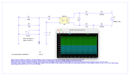
I simulated with a PC817A and it seems to work but I find that the resistors R1 and R2 are too low.
Regards,
Stef.
EDIT: The thread title is wrong. Read "measure" instead of detection.
I am working on a circuit that must measure a low AC voltage (between 5V rms and 10V rms) and generate a voltage for the AC feedback circuit (nominal value of 3V).
I am looking for help to choose the right optocoupler for this use.
I simulated with a PC817A and it seems to work but I find that the resistors R1 and R2 are too low.
Regards,
Stef.
EDIT: The thread title is wrong. Read "measure" instead of detection.
Attachments
Last edited:
I might have misunderstood your question. You want to detect a 5-10 mV AC voltage with an optocoupler? That is not possible, the diodes and optocoupler have a voltage drop of 0.6V and 1.2 each.
Also "low voltage AC current" is confusing.
Also "low voltage AC current" is confusing.
Sorry, I wrote too fast.
"low AC voltage detection" as the threat title no current as well.
It's between 5V and 10V AC not mV.
"low AC voltage detection" as the threat title no current as well.
It's between 5V and 10V AC not mV.
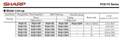
Any optocoupler could be used for this purpose. PC817, MCT2E, 4N35 and so on. An ultra fast opto like 6N137 is unnecessary unless the frequency is too high.
On the input side you only need 1 diode. That is important for the voltage drop.
The minimum AC voltage is 5V RMS. That is 7V peak. Since you use a capacitor to filter the pulsating voltage you can use that.
Voltage drop of 1N4148 = 0.7V
Voltage drop of PC817 = 1.4V max
Remaining voltage = 4.9V
Nominal current thru opto coupler diode: 5 mA.
One series resistor of 1k is good. Or 910 ohm if you have if.
The maximum allowed current thru the opto diode is 50 mA. So 10V RMS is also allowed.
Current transfer is 50% minimum. So opto transistor current will be 2.4 mA minimum.
I don't know what your output requirements are.
But you have to design it with this 2.4 mA min in mind.
It is custom to connect the emitter to ground and have a collector resistor.
Which means a low output when input current is present. I don't know if that is applicable for you.
Thanks for all theses details. I will look at all of this.
The circuit is to pilot the VFB pins from EG8010 ASIC chip but at very low voltage.
EDIT:
"Since you use a capacitor to filter the pulsating voltage you can use that."
Not sure to understand. but if we can remove a component, I vote for it.
The circuit is to pilot the VFB pins from EG8010 ASIC chip but at very low voltage.
EDIT:
"Since you use a capacitor to filter the pulsating voltage you can use that."
Not sure to understand. but if we can remove a component, I vote for it.
C1 filters the rectified voltage. For sine waves, the peak value is 1.4x the average value.
So instead of 5V minimum voltage at the input you can use 5 x 1.4V = 7V to calculate
the value of your series resistor.
Usually you want a smooth DC voltage. not a pulsating half-wave rectified sine.
The opto coupler would also have a interrupted signal out the output.
So instead of 5V minimum voltage at the input you can use 5 x 1.4V = 7V to calculate
the value of your series resistor.
Usually you want a smooth DC voltage. not a pulsating half-wave rectified sine.
The opto coupler would also have a interrupted signal out the output.
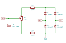
Usually D2 is put in series with R2. Like your previous schematic. But this will also work.
On the output it seems you have a 5V supply. But your digital input is 3.3V? is that the reason for VR1 and R5?
Either use the 3.3V supply for the transistor in the opto coupler, or use a clamping diode from the collector to the 3.3V supply. Or don't you have access to the 3.3V supply?
On the output it seems you have a 5V supply. But your digital input is 3.3V? is that the reason for VR1 and R5?
Either use the 3.3V supply for the transistor in the opto coupler, or use a clamping diode from the collector to the 3.3V supply. Or don't you have access to the 3.3V supply?
That seems to be a theme here.Sorry, I wrote too fast.
So what are your specs exactly? You want to detect low AC voltage. How low? You also want to detect low AC current? How low? And which current? The load current? I don't see anything in your schematic that would measure the load current. Or are you talking about the current draw of the detector circuit?"low AC voltage detection" as the threat title no current as well.
What is the maximum voltage the circuit will experience? Is galvanic isolation needed?
Personally, I'd be inclined to measure the peak AC voltage with a simple peak detector (three components). Then use a comparator to compare the peak voltage against some reference. You can now get comparators that'll run at uA.
With the optocoupler you'll run into an issue where you might get the circuit to work well, once. Then build it again with an optocoupler from a different batch and you'll have to re-tweak the component values because of the difference in current transfer ratio.
Tom
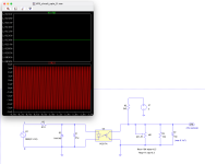
The last circuit I posted doesn't work. I must have done it wrong. I'll have a look tomorrow.
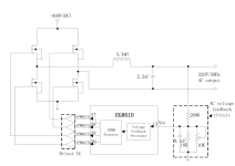
The goal is to isolate the AC voltage from the EG8010 ASIC. There's some 23KHz hanging around and I would prefer to physically isolate them.
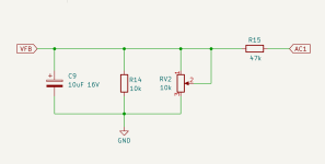
Otherwise, I'm currently using this simple circuit that works in the first diagram.
The second diagram comes from the datasheet. I modified the circuit to work between 5-10V and I would like to see if passing the AC feedback to the optocoupler would be useful.
In the AC feedback processor.
Overvoltage protection is set at 3.15V.
Undervoltage protection is set at 2.75V.
Stef.
The goal is to isolate the AC voltage from the EG8010 ASIC. There's some 23KHz hanging around and I would prefer to physically isolate them.
Otherwise, I'm currently using this simple circuit that works in the first diagram.
The second diagram comes from the datasheet. I modified the circuit to work between 5-10V and I would like to see if passing the AC feedback to the optocoupler would be useful.
In the AC feedback processor.
Overvoltage protection is set at 3.15V.
Undervoltage protection is set at 2.75V.
Stef.
Attachments
Last edited:
No, then the whole setup is wrong. You actually want to measure the voltage. Not detect whether it is present. It seems that you need to stabilize the output voltage and use a feedback.
The optocoupler will provide an on/off detection. That is what you wrote in your original post, that you needed a detection.
If you need a opto isolated feedback, you usually do that with a PWM modulated signal thru the opto coupler. At can be done analog as well, but then you need to linearize the opto isolation circuit. It can be done with an opamp and a second opto coupler. But it not trivial.
Besides, you have to be very careful with the time constants in the feedback circuit. Time constants in the same order of magnitude or greater as the time constant in the feed forward signal will cause instability.
Best is to look up an application to measure a voltage thru an opto isolator.
Besides, maybe you don't need galvanic isolation at all. This is for a 220V inverter. Since the secondary is not connected to earth, you won't get a shock when you touch one of the lines of the 220V circuit. That doesn't mean you don't have to be careful, touching both lines with both hands and this might have been your last post.
But the measurement circuit as drawn is fine for feedback. If you connect one of the output lines to ground, the 220V output is dangerous again.
But the measurement circuit as drawn is fine for feedback. If you connect one of the output lines to ground, the 220V output is dangerous again.
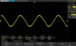
I have no fears with the use I make of it. I get between 5 and 10V AC at output with the circuit. 😉
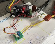
I should receive some PC817 this week. I will do some tests with the prototype that I use to develop the circuit.
Stef.
I should receive some PC817 this week. I will do some tests with the prototype that I use to develop the circuit.
Stef.
Attachments
avago / broadcom has an interesting design guide for all sorts of linear optocoupler applications. they have a linear coupler for normally used for motor current sensing . I have used it for voltage sensing. HCPL7800 series. also with an IL200 a low cost method of linear isolation can be achieved.
Hello,
I updated the first post in the topic to make this clearer. I couldn't update the topic title though (measure instead of detect). I also updated the LTSPice file.
The HCPL7800 is interesting but the chip is too expensive and the circuit around it takes too many components. I don't have the space on the PCB (no SMD use).
What is an IL200? I didn't find it but I know the IL-20 (pulse transformer).
Stef.
Last edited:
Not sure if this is relevant, but I have used something like this for years. You just have to scale resistances accordingly for the levels you need.
Thanks.
I have already tried a circuit of the same style. It works but does not provide any advantage over the basic circuit in direct connection with just a resistor. The circuit is useful if a transformer is used to convert the output voltage (up or down).
Attachments
Last edited:
it is renamed to HCNR 200, a single diode emitting to isolated receivers. from the same avago opto guide.


- Home
- Design & Build
- Parts
- Optocoupler for low AC voltage measurement