The circuit posted by @basreflex uses a special type of opto coupler which in compination with Q1 and Q2 linearizes the transfer. The circuit will transfer analog voltages more or less linearly to the output. This is achieved by feedback from the LED to PD1. PD2 will follow this behavior. It is the same principle as I mentioned before, using 2 opto couplers and an opamp. In this circuit the opamp function is performed by Q1 and Q2.
Since you already ordered the PC817, it is possible to use the same circuit with 2 opto couplers and have a linear voltage at the output. The accuracy will be not as good as with HCNR200, but still usable. It is used in a feedback circuit, non-linearity errors will be compensated by the feed-forward regulator.
However, the circuit is not applicable as-is. I have checked the EG8010 datasheet. For feedback, you need an AC voltage. That means you have to modify the circuit as given by @basreflex so the input is biased at approximately midway between the AC peaks. And the output should be AC coupled to the feedback input of the EG8010. As it is now, the negative part of the sine is either not transferred at all, or will be clipped. Also the supply voltage of 5V on the output will not be sufficient. You need to have 3V RMS to feed back into the EG8010. Which is about 9V p-p (!). The supply voltage must be at least 15V, but even better 20V for sufficient head room.
This is not rocket science, but it does require some careful analog design to get it right.
Now I know the function of the EG8010, why don't you just use a small transformer 220V - 6V and a adjustment potentiometer? It is 50 Hz after all what you have. A small transformer provides galvanic insulation, and really is a no brainer. Why the desire to achieve galvanic isolation thru and opto coupler?
Also, why don't you just feed back exactly as in the EG8010 application note? There is no galvanic isolation between the EG8010 and the 400V supply in your application, is there? You do not have a transformer between the switch and the output voltage, do you?
I am beginning to think that this question is an X-Y problem. https://en.wikipedia.org/wiki/XY_problem. I other words, you ask assistance for the implementation of the measurement circuit, but your actual problem is different. So our answers won't help you much.
Last edited:
I once used the HPCL7800 optoisolator to recreate a current for a current transformer input of a PV management circuit (solarlog) . there was a voltage reading missing, and the relative phase between voltage and current was not available. So I recreated a current by measuring the actual current and voltage and calculating the real power using a 1702 audio DSP and let it generate the 50hz at the proper amplitude as measured by the current, voltage and phase.
Well, I tried the circuit with the optocoupler (received today) that I gave on the first post of the subject. It does not work. With LTSpice I felt like it worked but in real life it doesn't. I no longer have the 7V output voltage and the sinus is bad. I do have 3V on the VFB pin though.
If I put the basic AC feedback circuit back, it works as it should (nice sinus and feedback AC working).
I could try another optocoupler / isolation solution as an experiment if you suggest a circuit.
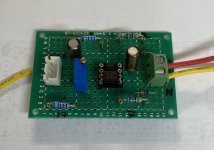
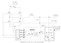
I'm giving you the full diagram of my project so that it's easier to understand. I also have a corresponding PCB but not yet printed. The prototype you saw pictured in one of my previous posts is just a base I made to run the EGS002 module (without the output filter, AC feedback, overcurrent and only one common 12V power supply). With the new PCB I could do some tests down to 5V, do some load tests at 5A and run it through the bench to see the spectrum.
Stef.
If I put the basic AC feedback circuit back, it works as it should (nice sinus and feedback AC working).
I could try another optocoupler / isolation solution as an experiment if you suggest a circuit.
I'm giving you the full diagram of my project so that it's easier to understand. I also have a corresponding PCB but not yet printed. The prototype you saw pictured in one of my previous posts is just a base I made to run the EGS002 module (without the output filter, AC feedback, overcurrent and only one common 12V power supply). With the new PCB I could do some tests down to 5V, do some load tests at 5A and run it through the bench to see the spectrum.
Stef.
Attachments


Also, why don't you just feed back exactly as in the EG8010 application note? There is no galvanic isolation between the EG8010 and the 400V supply in your application, is there? You do not have a transformer between the switch and the output voltage, do you?
That's what I'm going to do. I'm going to stick with the circuit as in the app note. It seems to work well. I let the model run for several hours at 7V 2A and it worked without any problems.
Using an optocoupler for the AC feedback is just an experiment to see if we gain something but I feel like it's like usual "keep it simple".
The final goal is to get 5Vac to power a 5U4G valve heating with this DC-AC board. It is very experimental to study feasibility.
Stef.
EDIT: Thank to the admin to have corrected the subject title.
Last edited:
Hello,
Here I am back on the subject.
I resumed my tests with an optocoupler because the last test with an optocoupler despite a poor quality sinus, I had seen that I had gone down to 2.5V.
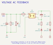
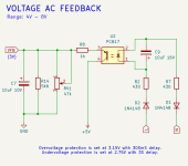
By dint of testing, I found a configuration that works to output 6.3V with a clean sinus (i.e. go below the 8V of the basic configuration). See the diagram.
When I turn the RV1 trimmer, I can adjust between output between 6V and 8V.
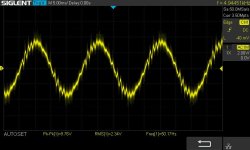
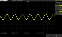
I drew 1.4A in 6.3V without any problem. See the scope curve.
I conclude that it must be possible to find a configuration that could work between 5V and 7V but I can't find it. There are too many parameters between the input resistors R2/R7 and the resistors on the other side of the optocoupler (R8, R14 and RV1).
I would need some help to try to formalize this configuration if possible. I lack theoretical basis.
Stef.
Here I am back on the subject.
I resumed my tests with an optocoupler because the last test with an optocoupler despite a poor quality sinus, I had seen that I had gone down to 2.5V.
By dint of testing, I found a configuration that works to output 6.3V with a clean sinus (i.e. go below the 8V of the basic configuration). See the diagram.
When I turn the RV1 trimmer, I can adjust between output between 6V and 8V.
I drew 1.4A in 6.3V without any problem. See the scope curve.
I conclude that it must be possible to find a configuration that could work between 5V and 7V but I can't find it. There are too many parameters between the input resistors R2/R7 and the resistors on the other side of the optocoupler (R8, R14 and RV1).
I would need some help to try to formalize this configuration if possible. I lack theoretical basis.
Stef.
Attachments

Last edited:
I have the same prototype board than in the video. 😉
I found it. I put a trimmer on R14 and adjusted to 5k6 to reset VR1 to the middle. I can now wander between 4V and 8V.
When I cut the load resistor, the module resets almost instantly to 5V. Same in the other direction. It's super responsive. So I always have the same voltage with or without load.
When I turn on the module, the sinus comes back after 3 seconds, slowly increasing. Nice softstart.
Attachments
- Home
- Design & Build
- Parts
- Optocoupler for low AC voltage measurement