@camplo A good discussion on sub topology variants. I don't need the bandwidth you require, and I typically stop at 80Hz, using BR boxes. I do like (want) the higher sensitivity by increasing Sd via multiple drivers. The V arrangement will not fully cancel mechanical vibrations, but the opposed drivers with V-wedge will cancel. I'm also a fan of Newton's 3rd law, as it's a bonus to have the drivers move without cabinet vibrations. I will be creating some AKABAK BEM models of this arrangement (but I use 12" subs) to see how it compares to my usual (easy ) BR box. These results might be applicable to your situation if you wanted more insight.

View attachment 1408232
Does anyone know the source of the Null at ~260hz... The outer edge of the woofers distance correspond with the Null so maybe that is the source.
I attribute it to the normal 1/4WL slot-width cancellation frequency. In the case of this wide-tapered 90 degree slot, I figure the average distance between the cones, aka the average slot width is a little more a foot. So I think any cancellation in the 250-300Hz range ties well with 1/4WL slot physics.
Imo, there's no escaping slot width cancelation, or at least I haven't seen a way yet. It's a big part of the reason I don't think slot loaded is a good idea if trying to use sub beyond "true sub territory".
That narrow width and short depth should simply be a diffraction grate, horizontal directivity should be over 90 degrees as high as 500Hz.I will say out of all of them, I sort of prefer the traditional V slot.
If I go this route with a 5" mouth I think it still works out, but directivity, I wonder.
If I recall, you still have a pair of 15" front load cabinets, just "V" them up and listen and measure if you want to know, rather than wonder.
For what it's worth, this is what horizontal directivity of 10" with side plates cutting the slot width to 5" looked like out to 100 degrees (50 degrees off)
I think the null around 350Hz was a ground bounce cancellation, but dispersion was wider than 100 degree past the bandpass at 1600Hz.
I don't expect the 5" "V" with 15" would result in as predictable dispersion due to the depth of the slot causing a variety of off-axis constructive and destructive interference.
Art
opposed drivers with V-wedge
The circular slot isn't completely unlike the V Slot. The most effect move is to get rid of parallel walls.
If I wanted to keep the height the same as the woofer ( I do) here are some ideas. The overlap issues should be well out of the passband. These profiles should be able to be modelled in horn resp to some extent.
The potential to design something to offset the horizontal reflections but honestly the woofer geometry gets rid of a good amount of parallel surfaces on that axis. If you are using woofers with increasing sensitivity in the HF like I do, the response of the sim of just a circular slot like pictured in the beginning looks pretty good given the null is moved up considerable. Increasing the amount of non parallel walls should only benefit the situation.
Last edited:
If the Circle by itself itself doesn't satisfy you FR needs, damping half the the slot to the rear, seems to still do the trick. I have big bag of safe n sound (12000mks rayls/m) that I got from HomeDepot, but I model using lower damping rating to hedge the bets (6000mks rayls/m) . I've got a little bit of Rockboard 80 (53000 mks rayls/m) also.
I just need to make it to 400hz, which will suffice for a >300hz.
Takes way longer than it looks. The piece is something like 29"x26", 3/4" ply with kerf cuts a smidge over 1/16th deep spaced at 1/4". I need 4 half circles, 2 large 2 small
Large
Inner Diameter (ID): 16.65"
Starting Material Length: 26.775"
Small
Inner Diameter (ID): 14.188"
Starting Material Length: 22.802"
This should create half circles that cup the mounting hole diameter of the 15"&18" woofers.
Laminating bendy plywood eliminates that kerf mess.This should create half circles that cup the mounting hole diameter of the 15"&18" woofers.
That said, curves are not warranted for what you want to achieve.
I try to keep you close, without being too annoying... Its a thin line, but as usual, thank you lol... The kerf mess is definitely a mess. It also adds mass off the rip. If one were to go the bendy plywood route, how would advise to reinforce? Epoxy good enough aye?Laminating bendy plywood eliminates that kerf mess.
That said, curves are not warranted for what you want to achieve.
I simulated curved rear baffle... what is it I want to achieve and how do I get it?
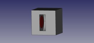
I mean tto post this here, not the main thread. This is supposed to show the mounting holes versus the drivers... The shaded parts of the woofers represent the mounting holes, they are smaller than the woofers themselves. The slot has to be taller than the woofers are so there's some room for a slightly expanding line from the mounting hole to the mouth. In the actual construction I am not sure how this will play out but I will try n make the best out of what I can. I am not an expert, far from it.

Whoops. I meant that there is only 1/16th inch left of material in the kerf joint😊1/16"
Don pictured above; 2 slotted sections, one for 15"s one for 18"s.
They are mounted on the inside of the baffle wall to slightly smaller holes than the woofers. The holes in the baffle, would be cupped by the kerfed baffle. The diameter of the hole leading to the slot is smaller than the slot height thus the top/bottom baffle can expand from halfway in the slot to the terminus
For the small throat size you are considering, lamination to ~3/4" (18mm) would not require reinforcement.If one were to go the bendy plywood route, how would advise to reinforce? Epoxy good enough aye?
I'd use wood glue for gluing plywood, unless planning to submerge it.
In the context of this thread, "High Output Subs that play 20Hz to ≥200Hz" I can't tell anymore.I simulated curved rear baffle... what is it I want to achieve and how do I get it?
Curved surfaces are not required to reach as high as 1200Hz.
Whoops. I meant that there is only 1/16th inch left of material in the kerf joint😊
Don pictured above; 2 slotted sections, one for 15"s one for 18"s.
They are mounted on the inside of the baffle wall to slightly smaller holes than the woofers. The holes in the baffle, would be cupped by the kerfed baffle. The diameter of the hole leading to the slot is smaller than the slot height thus the top/bottom baffle can expand from halfway in the slot to the terminus
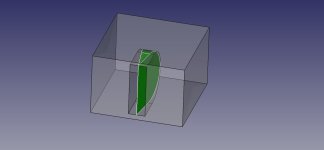
Like this? A slot with a curved rear surface? I left out any wedge or front compression chamber.
Can you export your Hornresp txt files that you used for the 18" and 15"?
Attachments
Don I attached the filesLike this? A slot with a curved rear surface?
The curve literally cups the rear 50% of the woofer diameter. And then a straight exit to the terminus from there would be more accurate. Its not literally cupping the woofer because the woofer is mounted to the side of the baffle inside the box. The slot is cupping the half the radius of the baffle hole the woofer is mounted to.
Larger Circle:
woofer 18.6" mounted to 16.65" baffle hole
Smaller Circle:
woofer 15.2756" mounted to 14.188" baffle hole.
The big slot height can be 16.65" and the small slot height 14.188" but the ramps would bring it out to about the same as the correlating woofers, so 18.6" and 15.27" is likely the better way to rough it for a slot height dimension. In HornResp I'm gonna use 15.5" and 18.5" for slot height just to keep it simple.
Both slots are 5.5" wide
This is going to run up to as high as 300hz potentiallyWhat about not closing the slot off at one end?
Attachments
Last edited:

- Home
- Loudspeakers
- Subwoofers
- High Output Subs that play 20Hz to ≥200Hz