Finally some progress. The psu boards are here. Tests so far go very well. Tomorrow I will rebuild my PSU into a new fancier case


There we go
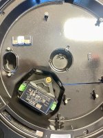
The new PSU cooking slowly after initial tests
Unfortunately, I have had this galaxy case for so long that I have no idea where its lid is

With this opportunity, can someone with an American SL1200 verify something please?
For 110V, the two primaries are wired in parallel? Like black connects to blue and white to brown?
The new PSU cooking slowly after initial tests
Unfortunately, I have had this galaxy case for so long that I have no idea where its lid is
With this opportunity, can someone with an American SL1200 verify something please?
For 110V, the two primaries are wired in parallel? Like black connects to blue and white to brown?
I finally got some time to work on the final pcbs.

Everything seems to work ok on the main circuit.

I did not have any screw terminals, so I had to test it as it is for a bit. Fortunately the part I managed to find fits nicely on the pcb

Unfortunately it seems that I am too tired to properly experiment with the TVS, as I managed to not only burn the part, but also melt the hook terminals of my PSU.

The part I tried was TP5KP20A. It has a working voltage of 20V and seemingly a steep A curve after that.
The point is to have 0 or some minor current passing through during normal operation (20-21V) and then have it pull 1A at around 23-24V so that it triggers the pptc fuse before reaching its 8W limit.
The problem is that its curve is not as steep. And it reached 1A at around 32V. And of course this meant >12W, a blown part, and melted terminals
Having a look at the datasheet, it seems that 1A is probably near its rated maximum clamping voltage at 32V. So if I had to guess, I would next choose TP5KP14A to experiment. It has a working voltage of around 16V, meaning at 20V it will pull a few hundred mA, meaning if we are lucky it can also replace the preloading resistor. And then it will reach its peak current at 23.2V, which is ~7,2W before it blows the fuse. I would prefer it a bit lower but it could work. Or I can look for a part with a steeper curve.
As for the preregulator on the PSU to drop some voltage before the main regulator, I am not really sure it makes sense. Too much complexity for such a trivial thing to gain. So I just replaced the stock transformer with a small toroid that I had around. And the regulator now runs much cooler.
Everything seems to work ok on the main circuit.
I did not have any screw terminals, so I had to test it as it is for a bit. Fortunately the part I managed to find fits nicely on the pcb
Unfortunately it seems that I am too tired to properly experiment with the TVS, as I managed to not only burn the part, but also melt the hook terminals of my PSU.
The part I tried was TP5KP20A. It has a working voltage of 20V and seemingly a steep A curve after that.
The point is to have 0 or some minor current passing through during normal operation (20-21V) and then have it pull 1A at around 23-24V so that it triggers the pptc fuse before reaching its 8W limit.
The problem is that its curve is not as steep. And it reached 1A at around 32V. And of course this meant >12W, a blown part, and melted terminals
Having a look at the datasheet, it seems that 1A is probably near its rated maximum clamping voltage at 32V. So if I had to guess, I would next choose TP5KP14A to experiment. It has a working voltage of around 16V, meaning at 20V it will pull a few hundred mA, meaning if we are lucky it can also replace the preloading resistor. And then it will reach its peak current at 23.2V, which is ~7,2W before it blows the fuse. I would prefer it a bit lower but it could work. Or I can look for a part with a steeper curve.
As for the preregulator on the PSU to drop some voltage before the main regulator, I am not really sure it makes sense. Too much complexity for such a trivial thing to gain. So I just replaced the stock transformer with a small toroid that I had around. And the regulator now runs much cooler.
Pass DIY Addict
Joined 2000
Paid Member
Nice work! For the TSV, I’m thinking you voltage rating is too low at 20v plus/minus parts tolerance. When their working voltage is exceeded, they turn into clamping devices with a permanent short circuit. Since the SL-1200 PSU runs on 21v, it is possible that you’ve overshot the limit of the device and caused it to short, hence the melted clips.
Given that this PSU already uses a step down transformer and you have a CRC filter on your board, what is the purpose of the TSV? What you have in place will greatly mitigate the likelihood of an overvoltage event.
The SL-1200 will draw somewhere near 12-13w at maximum for start/stop when the strobe and stylus needle are illuminated.
Last edited:
Nice work! For the TSV, I’m thinking you voltage rating is too low at 20v plus/minus parts tolerance. When their working voltage is exceeded, they turn into clamping devices with a permanent short circuit. Since the SL-1200 PSU runs on 21v, it is possible that you’ve overshot the limit of the device and caused it to short, hence the melted clips.
Thanks. Yes exactly. The thing is that you have to find a part that behaves as you want it. The 20V rating does not mean that it short circuits with anything above it. It does not act like a zener or a reference. The current ramps up slowly as the voltage rises. At 20-21V it was drawing nothing so everything was ok. At around 24V it started drawing some mA and it increased almost linearly up to around 30V. Above that it clamped fast to a short circuit. Ideally I need something that draws a couple hundred mAs max at 20-21V. And it clamps at ~23-24V before the voltage becomes dangerous for the ICs and before the TVS exceeds its W rating.
Given that this PSU already uses a step down transformer and you have a CRC filter on your board, what is the purpose of the TSV? What you have in place will greatly mitigate the likelihood of an overvoltage event.
I am going to experiment a lot with the regulators and the main board, and I already have burned a set of ICs because I have passed ~35V by accident. It's just a "piece of mind" part.
Pass DIY Addict
Joined 2000
Paid Member
Ha, I’ve toasted my share of TSV devices as well. I built a power sequencer/filter for my theater system and got a handful of 120v devices as well as a bunch of 60v devices (for 60-0-60v balanced power). With my first round efforts, I mixed up the voltages and it took me a while to discover why I kept popping fuses 🤣.
Sorry to hear you burned a SL-1200 board
Sorry to hear you burned a SL-1200 board
Hi everyone, thought I’d join in a bit on this thread as I’m just refurbishing a 1200 mk5g at the moment and putting in a switch mode PSU. All the information in this thread has been amazing, thanks to all the contributors! At the moment I’m replacing as many of the caps on the main PCB as possible with either Nichicon muse for electrolytic or Wima poly caps everywhere else… not going crazy though, just changing the parts that look like they need it or aren’t measuring well. I’ve just test printed a mount for the PSU this afternoon which fits perfectly, so on to the next steps… For now I’ll leave you with a photo of the new PSU mount.
Attachments

Hey all,
I also wanted to mod my sl-1200 mk2 but because I'm really not that good with understanding electronics I've come to conclusion that this mod https://theartofsound.net/forum/sho...-externalising-PSU-from-your-Technics-SL-1200 is the one for me as I'm only moving parts around that already exist. I tried to understand the PSU mod and the bit about regulators but nope. I don't get it.
I mean @6L6 did a wonderful job documenting everything so it's definitely a me problem.
K.I.S.S.
There's still a lot to gain by moving the trafo and PSU outside so that's what I'm going to do while the KAB tone arm mod kit is in the mail.
However, in the link I've provided a user OneyedK says "...while you're at it, replace C1 with 1000µF/50V. Have a look at the underside of the pcb, as you will notice, solder pads and holes are there to accommodate an axial cap, as the radial version will be too tall. A lot of decks are equipped with a 470µF/50V, while the schematic still states 1000µF (the correct value). No wonder that a lot of people claim impressive results with aftermarket psu's."
Maybe they post here too who knows shrug

So ok, replace one cap that I can handle but then while I was looking under the hood I noticed a capacitor in the PSU board. It's a sizeable one and with the values 0.047uf 450V. What does it do and is there a benefit replacing it after some 38 years of service?

I mean I guess recapping the whole thing after 38 years of service isn't that bad of an idea but I'm afraid it's out of my patience / skill level.
Anyway, thanks for reading and if you've got any suggestions for me about my upcoming PSU project let me know 🙂
I also wanted to mod my sl-1200 mk2 but because I'm really not that good with understanding electronics I've come to conclusion that this mod https://theartofsound.net/forum/sho...-externalising-PSU-from-your-Technics-SL-1200 is the one for me as I'm only moving parts around that already exist. I tried to understand the PSU mod and the bit about regulators but nope. I don't get it.
I mean @6L6 did a wonderful job documenting everything so it's definitely a me problem.
K.I.S.S.
There's still a lot to gain by moving the trafo and PSU outside so that's what I'm going to do while the KAB tone arm mod kit is in the mail.
However, in the link I've provided a user OneyedK says "...while you're at it, replace C1 with 1000µF/50V. Have a look at the underside of the pcb, as you will notice, solder pads and holes are there to accommodate an axial cap, as the radial version will be too tall. A lot of decks are equipped with a 470µF/50V, while the schematic still states 1000µF (the correct value). No wonder that a lot of people claim impressive results with aftermarket psu's."
Maybe they post here too who knows shrug
So ok, replace one cap that I can handle but then while I was looking under the hood I noticed a capacitor in the PSU board. It's a sizeable one and with the values 0.047uf 450V. What does it do and is there a benefit replacing it after some 38 years of service?
I mean I guess recapping the whole thing after 38 years of service isn't that bad of an idea but I'm afraid it's out of my patience / skill level.
Anyway, thanks for reading and if you've got any suggestions for me about my upcoming PSU project let me know 🙂
Hey @streetsepi, that orange cap is a film cap and is highly unlikely that it would need changing. It is mainly the electrolytic caps (aluminium can looking) that dry out and will need replacing. For what it’s worth I just recapped mine after 15 years and all the caps measured ok, but that doesn’t mean they didn’t need replacing. If you don’t have the patience, then just do the main cap you pointed to, but you’d be better off replacing any of the other electrolytic, rather than the orange one in my opinion….I mean I guess recapping the whole thing after 38 years of service isn't that bad of an idea but I'm afraid it's out of my patience / skill level.
Thank you kindly!
I think I'll do these incrementally so step 1 is the PSU/trafo/1000uf cap. Well technically step 1 is adding weight to the platter but it's really simple to do so I don't count it. So simple infact that I forgot to mention it earlier heh.
Step 2 will be the KAB tonearm mod
Perhaps in the future far far away step 3 might be the total recapl.
I’d suggest not adding weight to the platter. If you want to do something get an Acromat or cork mat.
The fluid damper is good. So is a tonearm rewire.
IMO
The fluid damper is good. So is a tonearm rewire.
IMO
There should be no problem with adding a bit of weight to the platter. The KAP poly-metal mat should do a fair bit of good for reducing vibration transfer. That said, if still using a MKII, I'd highly recommend getting the new thrust plate and wax to beef up the bearing support, and get enough oil in there to prevent wear. The external transformer mod is probably still the biggest bang for the buck sound quality improvement (the one thing I never did on a MKII, but have heard the massive improvement on someone else's deck), but almost all of the mods available at KAB are worthwhile.
Thanks everyone!
I'll record and see if it nulls (I've recorded unmodded already) if it nulls hard then there's nothing but dead weight on the platter. If it doesn't it's up to listening tests and subjective biases! Same obviously goes for every other mod in the pipeline.
I did look into SMPS' but getting a decent with good ripple specs to Finland was somewhat expensive so I thought that with most of the required bits that's already in the turntable then you know... Cheap, simple_ish and hopefully fun and educative.
Thanks everyone once more, I'm hoping I get to post some progress sooner rather than later!
I’d suggest not adding weight to the platter.
I'll record and see if it nulls (I've recorded unmodded already) if it nulls hard then there's nothing but dead weight on the platter. If it doesn't it's up to listening tests and subjective biases! Same obviously goes for every other mod in the pipeline.
Ah yes I forgot about that thrust plate bit! Read about it in KAB site and I believe there was some tests with ptfe discs in this topic. I'll give it a try in the future for sure. And for sure yeah I want to try the external trafo mod since basically it's been mainly positive feedback about.I'd highly recommend getting the new thrust plate and wax to beef up the bearing support, and get enough oil in there to prevent wear. The external transformer mod is probably still the biggest bang for the buck sound quality improvement
I did look into SMPS' but getting a decent with good ripple specs to Finland was somewhat expensive so I thought that with most of the required bits that's already in the turntable then you know... Cheap, simple_ish and hopefully fun and educative.
Thanks everyone once more, I'm hoping I get to post some progress sooner rather than later!
Hey all,
I thought I'd write a follow up now that I've messed around a bit with weights. Still waiting for the tonearm mod set to mail over seas to me. Also figuring out a nice looking box for the trafo/psu so that's on hold too.
Spoilers: I was actually pretty surprised with the results of my null tests with platter- and record weights.
So I ordered a platter weight cut from 3mm sheet metal with a diameter of 300mm and a 7,5mm spindle hole cut out. This weighs 1652g and is laid on top of original Technics rubber mat; on top of metal is cork mat and there's also a record weight cut from 8mm steel with 100mm diameter and 7,5mm spindle hole weighing in at 487g. So in total I've now added 2139g (~4.7lbs) of metal on the platter and sorta / kinda isolated the added metal from platter with the rubber mat. Thank you Oulun Palametalli for the plasma cutting. Great precision work as always.
I recorded audio files with RME ADI-2 Pro FS R Black Edition (geez that's a mouthful) straight from turntable output so there's no hum or noise generated by any analog amps other than what's in the input of the DAC. Gain was added digitally in DAW. Null test uses digital phase flip. Files are 32bit 96k. Overkill but whatever. DAW is Logic Pro X and the recorded song is probably better kept a secret because silly legal reasons. I wouldn't want to admit to single handedly killing the recording industry by home recording.
These are the recorded variations:
1. standard SL1200mk2 setup so platter + rubber mat
2. standard SL1200mk2 setup, this recording is to check how hard it's even possible to get null because of wow and flutter randomness
3. rubber mat + 3mm sheet + cork + record weight
4. rubber mat + 3mm sheet + cork
5. 3mm sheet + cork + record weight
6. 3mm sheet + cork
Firstly recordings 1 & 2 do not hard null. They cancel like ~40dB (RMS level drop from -36db to -76dB @50hz) in the 20-200Hz_ish region but higher the frequency less cancellation. It's not like higher transients would come louder or anything, mid to high freqs just don't seem to cancel as much.
With recordings 3-6 the cancellation of the low to mid region is much less for example with recording 3 RMS level drop to only -50dB @50hz. So definitely the bass is different and so is the rest of the range.
How to describe the effect is oscillation. The cancellation gets more pronounced in a wave type motion and through out this wave you can hear obvious comb filtering. I believe this is from added stability to the platter through inertia so what actually oscillates is the original recording ie. stock SL1200mk2.
Subjectively I prefer how the heaviest loaded recording (#3) sounds; there's less mud in lower mids which probably in turn causes vocals and mids in general seem to come more focused and forward but not in abrasive way. Everything is kinda just "more there" in their respectful places I guess. Less mud and sharpened (or tightened or more solid) stereo image in other words.
This cost me 50euro with shipping and three hours for recording and listening. And of course 5minutes in CAD for the weight drawings.
So mod #1 down for my former DJing deck, welcome to the world of hifi friendo <3
Thanks for reading 🙂
You've changed the vertical tracking angle quite a bit with adding a 3mm weight and a cork pad.
Right when I thought I'm doing things proper I overlook something like this. Oh well, more recording to do tomorrow. Thanks for pointing this out!You've changed the vertical tracking angle quite a bit with adding a 3mm weight and a cork pad.
Good evening,
I adjusted the tonearm height, recorded the song with full load and had a brief listening session and basically everything I've stated earlier still stands; however the tone is a bit different.
I guess this is the vertical tracking angle at work here and the effect of the added mass on the platter still does have somewhat significant effect when comparing to stock SL1200mk2 setup.
Thanks once again for the tonearm height heads up 🙂
I have played a lot with different things this past decade. The SL1200 is definitely sensitive to such changes. And while adding weight and mass to the platter has some effect, my observation is that most of it is because of how flimsy the die cast chassis is at the point where the spindle touches it. Further pressure from the extra platter weight seem to tame vibrations and its ressonance a bit. The one thing with the greatest impact you can do is get a ~2cm ball of wax and put it below the spindle's thrust pad, so that it's in tight contact with the chassis instead of floating in the air. The improvement punches you to the face, And after that, the changes from different mats etc were less prominent, at least to me.
Some extra things could further improve things and I want to try them at some point. Like some dynamat under the aluminum chassis to further reduce vibrations. Or some wax or glue to improve the interface with the plastic plynth. BTW my plastic plynth has started to deteriorate a bit. It feels brittle and it has started chipping. So this might also benefit from some treatment with some material to imrpove its stability and its interface with the aluminum.
Some extra things could further improve things and I want to try them at some point. Like some dynamat under the aluminum chassis to further reduce vibrations. Or some wax or glue to improve the interface with the plastic plynth. BTW my plastic plynth has started to deteriorate a bit. It feels brittle and it has started chipping. So this might also benefit from some treatment with some material to imrpove its stability and its interface with the aluminum.
- Home
- Source & Line
- Analogue Source
- Technics SL-1200 DC Power Supply