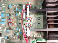
Image of the entire amplifier board as well as hi-res output amplifier board.
Don't under any circumstances remove DBT...for now...I suspect something else is going on.
Don't under any circumstances remove DBT...for now...I suspect something else is going on.
Image of the entire amplifier board as well as hi-res output amplifier board.
I also put the scope on the power amp input - (junction of the 100k and 4k7 resistors) to look for the switch-on pulse from the pre-amp as described in the maker.pro thread I referenced in my previous post. Sure enough, at about 4 seconds from power-on there was a 100ms 12v (!!) pulse into the power amp. I expect that would overdrive it horribly and potentially trigger oscillation?
Googling about problems with Audiolab 8000A/P/S, history shows that everyone has had problems with decoupling capacitors on the amplifier at one time or another - these are blue Elna RE2 4u7/63V electrolytics on the left and right side of the ballast resistors of the output transistors as well as 47u/16V in parallel with 4V7 zener diodes as voltage references of the constant current source BC846B for 2SK389. Actually, all the ELNA RE2 type electrolytics in the amplifier had gone low capacity/high ESR (dried up, due to the heat and age), so change them, if you haven't already.
Attachments

Thanks - I have changed the pair each side of the ballast resistors on the channel towards the upper part of the picture but none of the others you mention. I'll try changing those and report back.
OK, I changed the six capacitors but still getting oscillation.
It does look like the frequency of the oscillation has changed and in the brief time I allowed it to happen the scope frequency counter said about 20kHz whereas before I think it was in the 300kHz area.
I then tried some 47uF caps on the 12v zeners that supply the differential stage. That didn't stop the oscillation either but it did keep those rails clean during oscillation - beforehand they got very noisy with about 1v of noise on them.
So, still stumped. I still wonder if this could be due to running via the DBT but I'm very reticent to try without!
Any ideas appreciated!
Back to 2nd paragraph of post #10. 300 khz is radio freq. Feedback line is a 4" long antenna leading to the gate of the dual FET. 2sk381? So you proved the FET is amplifying the RF? You have never really reported observation of gate source and drain voltages there to prove or disprove RF amplification. You just said muting the input stopped the oscillation.
If Fet is oscillating, you need to put RF damper at the FET end of the feedback line. I suggest a 6 turn inductor. 10 turns would not hurt anything. A ferrite bead on the feedback gate leg would perhaps also work. I'm sorry audiolab did not forsee in 1985 that everybody would carry a radio transmitter in their pocket, but that is the situation now. If you are not calling anybody, your cell phone is reporting your location to the tower every few seconds. So google can track you and send location specific ads. Cell phones emit radio frequencies. So does the tower <1 mile from your house. Continuously. You have not shown the input board part of schematic. It is possible RF is being picked up by long lines from the RCA jack input to the preamp board then on to the amp board. I have put 33 pf caps across the input RF jack which solved my AM radio pickup problem, but with the case off all the wires & traces before the dual fet transistor also form antennas for RF pickup. Maybe both gate legss of the dual fet need a ferrite bead.
If Fet is oscillating, you need to put RF damper at the FET end of the feedback line. I suggest a 6 turn inductor. 10 turns would not hurt anything. A ferrite bead on the feedback gate leg would perhaps also work. I'm sorry audiolab did not forsee in 1985 that everybody would carry a radio transmitter in their pocket, but that is the situation now. If you are not calling anybody, your cell phone is reporting your location to the tower every few seconds. So google can track you and send location specific ads. Cell phones emit radio frequencies. So does the tower <1 mile from your house. Continuously. You have not shown the input board part of schematic. It is possible RF is being picked up by long lines from the RCA jack input to the preamp board then on to the amp board. I have put 33 pf caps across the input RF jack which solved my AM radio pickup problem, but with the case off all the wires & traces before the dual fet transistor also form antennas for RF pickup. Maybe both gate legss of the dual fet need a ferrite bead.
Last edited:
I've collected some readings around the inputs of the 2SK389 when oscillation starts:
The input side:
Gate (pin 2): about 20mV p-p of oscillation around 0v.
Drain (pin 1): sits at around +2V with about 500mV of oscillation on it.
Source (pin 3): sits at a steady +100mV
Feedback side:
Gate (pin 6): has about 500mV p-p oscillation centred at around +200mV
Drain (pin 7): Sits at a steady 0v
Source (pin 6): has about 500mV p-p oscillation centred at around +200mV (looks very similar to the gate signal).
The oscillation frequency is looking to be around 16kHz to 20kHz since the capacitor changes.
I've tried with my mobile (cellphone) in flight mode and not and it seemed to make no difference. I can't do a lot about the local tower!
I think I mistook a constant current source/sink for a mute circuit!You just said muting the input stopped the oscillation.
With 20 khz oscillation you are going to need a lot more suppression than a ferrite bead or a 10 turn coil.
Maybe try different values at the 47 p cap paralleling the 2.7k feedback resistor. You can tack other caps on, you don't have to remove the 47 p
330 p to ground on the input gate is a pretty serious RF filter. My ST120 came with 62 p, upped to 180 pf by me to eliminate sports talk radio (AM band) coming in from 4 m rca cables.
You might try to parallel the 100 ohm from feedback gate to ground with 200 - 330 pf cap to ground.
indianajo -
So... I don't have many small pF caps to hand so I tried a 1000pF across the 47pF cap (the resistor on my board is 3.3k instead of 2.7k) and the oscillation is gone. I have some 22pF so I'll make up a small piece of strip board so that I can build up more gradually.
I need to double check but the full diagram in the service manual shows two of those 47pF/3.3k filters per channel - one gets connected when the speaker protection relay is normal (this is the one I modified) and another that gets connected when the speakers are connected. I'm not sure I understand why they have two and the relay swaps between them. Now that the protection relay operates the other unmodified filter gets switched-in instead of the modified one but the amp stays stable
Obviously that's a huge step up so I'll get some smaller values and try those. Is 1000pF likely to have an detrimental effects on the sound ? If I'm right about the switching of the filters then any audio effects will be limited to the headphones.
So, just to confirm, your thoughts are that by design the filtering of RFI was too conservative? Something I don't understand is why when the oscillation is at 20kHz filtering that I assume would cut off at much higher frequencies stops it (or stops it starting).
Thank you for your input.
I am saying audiolab's testing for oscillation under RF input was sleazy. There were 1000 w CB radios driving around in 1985. Not legally. I had a yellow pickup driving by emitting dogs barking the song Dixie continuously at one point in my audio experience. Maybe audiolab's checkout lab was in a metal building, which is a faraday cage of sorts.
You could do a frequency sweep test if you have such a device to see what response is 20-20000 hz with the 1000 pf cap. I don't have that, I have a hammond H182 organ sine wave generator that the frequencies stop about 7000 hz. I'm glad paralleling the feedback cap stopped the problem, as putting capacitance to ground from the gate of the feedback FET is likely to affect 20000 hz gain badly. There is a way to calculate how big the feedback capacitor should be, but I did not buy that book. Disk cap parallel the feedback resistor kills the gain on the high frequencies in the frequency domain. Make sure you buy CPO ceramic or mica caps. Film caps will have inductance which means they are not a short at high frequencies. Don't buy 50 v rated caps. A break in the speaker crossover could cause 100v or higher transients coming back from the speaker output.
You could do a frequency sweep test if you have such a device to see what response is 20-20000 hz with the 1000 pf cap. I don't have that, I have a hammond H182 organ sine wave generator that the frequencies stop about 7000 hz. I'm glad paralleling the feedback cap stopped the problem, as putting capacitance to ground from the gate of the feedback FET is likely to affect 20000 hz gain badly. There is a way to calculate how big the feedback capacitor should be, but I did not buy that book. Disk cap parallel the feedback resistor kills the gain on the high frequencies in the frequency domain. Make sure you buy CPO ceramic or mica caps. Film caps will have inductance which means they are not a short at high frequencies. Don't buy 50 v rated caps. A break in the speaker crossover could cause 100v or higher transients coming back from the speaker output.
Last edited:
The frequency shift at which the amp now oscillates in the kHz range is a consequence of better decoupling with the new capacitors. Layout and decoupling on this amplifier is very poorly executed. In order for the decoupling to be carried out (at least to some extent, without butchering the pcb), I suggest that instead of 4 x 4u7/63V, you put approx. 470-1000uF/63V (the largest capacity you can fit into the existing raster, taking into account that those with a smaller radius and toller are better, try to choose those of 120°C). On the bottom side of the pcb, put in parallel over those electrolytes approx. 100n-1u/63V film capacitors. In theory, these capacitors should be as close as possible to the electrode of the output transistor which is connected to the power supply line (in your case it is the emitter of 2SA1216/2SC2922 because the output transistor is essentially a Sziklai pair, a compound of 2SC4382/2SA1216, or 2SA1668/2SC2992 acting like a single transistor.OK, I changed the six capacitors but still getting oscillation.
It does look like the frequency of the oscillation has changed and in the brief time I allowed it to happen the scope frequency counter said about 20kHz whereas before I think it was in the 300kHz area.
I then tried some 47uF caps on the 12v zeners that supply the differential stage. That didn't stop the oscillation either but it did keep those rails clean during oscillation - beforehand they got very noisy with about 1v of noise on them.
So, still stumped. I still wonder if this could be due to running via the DBT but I'm very reticent to try without!
Any ideas appreciated!
Do the same for the 4 x 100n film capacitors on the left side of the 22Ω resistance (to the MPSA42/92 predrivers) on the +/-44VDC supply lines, same/similar values for the electrolytes, put the existing 100nF/63V film caps in parallel with the electrolytes on the bottom side of the pcb .
Btw, to prevent oscillations of components that have very high input impedance (such as gates on 2SK389 j-fets or bases of bipolar transistors, gates of M-fets) all components in contact with them like the 4k7 and 330pF on the input side, as well as the 2 x 3k3//47p + 100Ω on the output side, must be placed as close to the gates as possible, literally.
Under no circumstances should you attempt to operate the amplifier without DBT until all problems have been resolved. For your comfort, download Audiolab 8000S service manual and you will see that it states that a regulated power supply of +/-32VDC is used when diagnosing problems.
After a long delay I've done these changes, although 100uF was the largest I could fit at the suggested locations which is obviously much lower than recommended. I removed the feedback capacitor changes I made and I still have oscillation.I suggest that instead of 4 x 4u7/63V, you put approx. 470-1000uF/63V (the largest capacity you can fit into the existing raster, taking into account that those with a smaller radius and toller are better, try to choose those of 120°C). On the bottom side of the pcb, put in parallel over those electrolytes approx. 100n-1u/63V film capacitors. In theory, these capacitors should be as close as possible to the electrode of the output transistor which is connected to the power supply line (in your case it is the emitter of 2SA1216/2SC2922 because the output transistor is essentially a Sziklai pair, a compound of 2SC4382/2SA1216, or 2SA1668/2SC2992 acting like a single transistor.
Do the same for the 4 x 100n film capacitors on the left side of the 22Ω resistance (to the MPSA42/92 predrivers) on the +/-44VDC supply lines, same/similar values for the electrolytes, put the existing 100nF/63V film caps in parallel with the electrolytes on the bottom side of the pcb .
Next step is to add back the caps on the zeners for the 12v supply and see if that helps. After that I'll increase the 47pF caps in the feedback loop.
Further update, and a curious thing....
I've not put the 12v supply decouplers on yet but I have tried changing out the 47pF caps on the feedback loops.
A curious thing (to me) in the design is that the feedback loops come via the speaker protection relay and for both the relay contacts normal/off (and headphones) position and the speakers connection there are two separate sets of a 3k3 resistor paralleled with a 47pF. Not sure why one set is not used here.
Anyway, I found I had to increase the 47pF to 220pF to stop the oscillation. BUT I only changed those caps on the normal/off paths, The amplifier now comes out of protection and the relay switches over and is stable on the loop with the original 47pF caps.
It looks like something the power-up process does (I've previously said there's a 12v pulse delivered by the pre-amp on power-up that might be the cause?)
Any thoughts?
Last edited:
I cannot tell if you increased the feedback cap on the line that is connected to the output transistors at all times, or on the line that is disconnected from the output transistors when the relay is open.A curious thing (to me) in the design is that the feedback loops come via the speaker protection lay and for both the relay contacts normal/off (and headphones) position and the speakers connection there are two separate sets of a 3k3 resistor paralleled with a 47pF. Not sure why one set is not used here.
Anyway, I found I had to increase the 47pF to 220pF to stop the oscillation. BUT I only changed those caps on the normal/off paths, The amplifier now comes out of protection and the relay switches over and is stable on the loop with the original 47pF caps.
When the relay is open or changing from closed to open, the feedback pcb trace to there is a 12 cm antenna with an open end. Lots of high gain circuits will produce a burst of noise when attached to a relay that is open. I had trouble with that on a relay source switcher to an input channel of a TI DFSII at work in 1975. Huge burst of noise in the recorded data. That burst of noise could set the gain stages to ringing like a bell after hit by a clapper.
From what I can see, it probably won't help with oscillation, but it will definitely make the +/-12VDC power lines cleaner, and it will also help decouple the entire input stage from the rest of the amplifier.Next step is to add back the caps on the zeners for the 12v supply and see if that helps
As far as can be seen from the available schematics, the reason for this is how the output relay and the headphone output connector are connected. For the amplifier to work properly, the negative feedback loop must be closed, otherwise the output from the amplifier would be stuck on one of the power lines. In your case, when the amplifier is turned off, the output from the amplifier is directed through the relay contact to the headphone output connector. After turning on the amplifier, if the headphones are not plugged in, the output relay coil receives 0VDC directly from the power supply through the ground contact on the headphone connector itself, the relay is activated and switches the output from the amplifier to the speakers after the protection and relay drive circuits have done their part. If the headphones are plugged in, the output relay loses contact to 0VDC through the ground contact on the headphone connector, the relay is not activated and the output from the amplifier remains directed to the headphones.A curious thing (to me) in the design is that the feedback loops come via the speaker protection relay and for both the relay contacts normal/off (and headphones) position and the speakers connection there are two separate sets of a 3k3 resistor paralleled with a 47pF. Not sure why one set is not used here.
If there was only one set of 3k3//47pF, the negative feedback could not be closed for one of the above cases and the output from the amplifier would stick to one of the supply lines. See the connection between (d)-(d) and (e)-(e) on the attached schematic.
Attachments
Audiolab 8000A model 207.pdf has one page, the title page. When I try to scroll down, the pdf viewer crashes.
Thanks both. I realised the reason for the two separate sets of 47pF/3k3 just after posting.
The situation now is that changing the 47pF caps to 220pF (currently only on the lines connected to the normal/headphone/power-off side of the relay) the oscillation at power-on is quelled and the protection relay does operate about 4 seconds later meaning the feedback lines then go via the 47pF sets. The amp seems to stay stable.
At this point I tried measuring the various voltages against and found that touching the DVM probe on many points around the differential pair and the next set of transistors caused oscillation to start up. Ok, that won't happen in normal use but seems to indicate some inherent instability still? I might try changing the other 47pF to 220pF to see if that improves matters.
All the power amp electrolytics have been changed and the suggested new ones added albeit some of lower values than proposed due to space limits.
The initial oscillations seems to be provoked by the 12v pulse the preamp kicks out about 4 seconds after power-up but are now quickly stopped. Both channels are the same so doesn't seem to indicate a fault. The protection relay operate at about 8 seconds.
I'm still trying to get my head round what might have changed since the amp was new. As indianajo points out there's a lot more RFI these days but the correlation with the preamp startup pulse means that doesn't sit squarely with me.
PS. Still running on DBT with no output transistors! Now that the protection circuit is happy I think I need to make the leap to full mains supply.
I still cannot understand the relay arrangement, but double pole double throw relays are not usual for protection. The feedback line gets a kick of RF noise every time the relay contacts are between positions. Having the headphone jack connected while the amp is in protection makes no sense. If the amp is in protection because the output is producing DC, then destroying a headphone instead of the speakers with DC is a stupid idea.
That's what they do. Bizarre, I know. There's a contact on the headphone socket that feeds to the protection circuit, which controls the relay. If headphones are plugged in it breaks the circuit through the relay coil!Having the headphone jack connected while the amp is in protection makes no sense. If the amp is in protection because the output is producing DC, then destroying a headphone instead of the speakers with DC is a stupid idea.
- Home
- Amplifiers
- Solid State
- Audiolab 8000A popping fuses