Thats interesting idea about PFFB, i will tried it in my el cheapo chinese tpa3255

Fantastic 🙂I actually prefer the sound of no PFFB. It may get -7dB lower THD but at the low levels already intrinsic in the amp not sure if needed.
There’s a slick 50pF or 100pF post filter feedback developed by Bucksbunny that was shown to be even better than conventional PFFB. Basically, take output at speaker out and connect to input pin at chip via a 100pF NP0/C0G cap. It gets rid of overshoot and ringing.
Can you please show (draw ) how this is done in schematics ?
We should get confirmation from @bucks bunny , but from what I could gather, it looks like this based on simulations he made on a TPA311x.


I would connect the output of the amp with 100pF NP0/C0G (rated for 100v at least) to the input + pins like this:

I would connect the output of the amp with 100pF NP0/C0G (rated for 100v at least) to the input + pins like this:
Indeed this is the way I do it since.
Do not forget to add some series resistor 1k0 ~ 2k2 to each input and
drive with a low z op-amp output.
With open input, this circuit will oscillate wildly and auto-shutdown immediately.
Exact values can be found by experiment.
Assuming there is always some inductance in series with the speaker load
I recommend looking for best square wave response without load.
And there is NO BOUCHEROT required until somebody proves the contrary.
Last edited:
Bucks bunny : so you must use an extra op amp to do this ? Maybe a dual opa1612 ( one for each channel ) ?
So , if I understand : 100 pF in series from + loudspeaker terminal ,
to 2k2 resistor in series, to one side input of opa1612 , to output directly to + input leg of tpa 3255 ? No coupling cap needed after opa1612 ?
So , if I understand : 100 pF in series from + loudspeaker terminal ,
to 2k2 resistor in series, to one side input of opa1612 , to output directly to + input leg of tpa 3255 ? No coupling cap needed after opa1612 ?
I think the typical TPA3255 implementations always have an opamp driving the inputs through a typical 10uF DC isolation cap. Connect the 100pF after the DC isolation cap near the input pin.
A great low impedance opamp for audio is OPA1656 - these can drive 100mA. In same family is OPA1642 which has JFET input if you need that.
A great low impedance opamp for audio is OPA1656 - these can drive 100mA. In same family is OPA1642 which has JFET input if you need that.
Where i have put the resistor? After the 10Uf DC blocking cap series with 100pf or series before the op amp input? Thanks...this a biggest mod i ever seen for class D amp !Indeed this is the way I do it since.
Do not forget to add some series resistor 1k0 ~ 2k2 to each input and
drive with a low z op-amp output.
With open input, this circuit will oscillate wildly and auto-shutdown immediately.
Exact values can be found by experiment.
Assuming there is always some inductance in series with the speaker load
I recommend looking for best square wave response without load.
And there is NO BOUCHEROT required until somebody proves the contrary.
How is it an antenna? No worse than a speaker cable as it is after the filter. Also, properly implemented would be a trace on a ground plane short as possible from output to input. Similar to usual PFFB traces.
Probably the easiest way to implement this as a mod would be to use a very fine wire like wire wrap wire and connect from output to the through hole 10uF cap on the amp side via an SMT NP0 cap soldered to the pin on one end. Lay the wire flat to the ground plane of the board and tape with Kapton so it is flush with board. This reduces mechanical strain on solder connection as well.
Probably the easiest way to implement this as a mod would be to use a very fine wire like wire wrap wire and connect from output to the through hole 10uF cap on the amp side via an SMT NP0 cap soldered to the pin on one end. Lay the wire flat to the ground plane of the board and tape with Kapton so it is flush with board. This reduces mechanical strain on solder connection as well.
Last edited:
Just my 50 cent, switching and large film capacitors bad Blend, perhaps im mistaken, it has happened once or ? Twice, who cares, its new years eve and i finished two bottles of Wine .. with that said.. happy new year...may the world become a quieter place, where things that really matter take presedence
i dont think 100pF NP0/C0G is large film capacitor, its ceramic type...and happy new year too
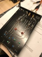
i got pic someone mod his Aiyima 07 to PFFB with successfully like this....How is it an antenna? No worse than a speaker cable as it is after the filter. Also, properly implemented would be a trace on a ground plane short as possible from output to input. Similar to usual PFFB traces.
Probably the easiest way to implement this as a mod would be to use a very fine wire like wire wrap wire and connect from output to the through hole 10uF cap on the amp side via an SMT NP0 cap soldered to the pin on one end. Lay the wire flat to the ground plane of the board and tape with Kapton so it is flush with board. This reduces mechanical strain on solder connection as well.
Attachments
That’s a nice implementation. Back in the the TPA311x days I had a snubber mod that worked pretty well and was simple. Also P2P conformal wire like above.
Be aware that the exact values depend on your actual output filter and should be found by experiment.
And where is it better to place the PFFB components? right after the filter or near the op amp?i got pic someone mod his Aiyima 07 to PFFB with successfully like this....
- Home
- Amplifiers
- Class D
- TPA3255 - all about DIY, Discussion, Design etc