
Thank you very much.
To reduce this effect I will use silver plated wiring, I hope this solution will help me to reduce it.
To reduce this effect I will use silver plated wiring, I hope this solution will help me to reduce it.
Just posting to say how very nice sounding the Ubib 1.3's are with the Soekris dam2941. Thanks Salas and also euro21 for your suggestions.
I used Vishay MRS series for R1 and also replaced Vrr with a fixed resistor.
I recently purchased a WiiM Pro for streaming and using its digital coax to connect to the dam2941. Sounded a tad thin with the stock supplied SMPS travel charger 5v 2A with USB C connector to Wiim Pro streaming Tidal Connect. I tried a Lenovo laptop charger 65w and was pleasantly rewarded with a much fuller sound. Salas which of your PSU designs might help here?
Thanks. Nash
Attachments

Hi, well done with your 2941. Nice to know it sounds good to you with UltraBiB 1.3. As linear alternative to SMPS adapter there's my L-Adapter PSU design.
Hi. Ive recently built two ubibs1.3 on official boards with standard Tea-bag supplied kit parts. It is configured 4.75V and ~130ma. It powers analog section of my r2r dac (ladder) which consumes ~30ma per side (one ps for each channel). All works fine and stable. One remark - heatsinks are barely warm.
Previously i have used Paul Hynes PR3 powers supplies for this purpose.
Sound observations: increase of resolution, sound energy and increase of voices sibilance (T's and S'es are more pronounsed). Last part about sibilance bothers me. Though i love increase of nuance i hear in my music. So i wondering if i could tweak my ubibs?
Maybe anyone has suggestions what could be done?
Thanks in advance.
You could evaluate subjective synergy of: a. Increase standing current since its barely warm. b. Bypass C2 with a small MKP underneath. c. Increase C2 value.
30VA, 9.7Vac.Hi, what ac output and VA size is the transformer(s)?
Thank you.You could evaluate subjective synergy of: a. Increase standing current since its barely warm. b. Bypass C2 with a small MKP underneath. c. Increase C2 value.
What values of caps you would suggest to try?
0.1uF MKP bypass, 1000uF C2. Evaluate in steps. Like do step (a), listen, is it enough? If not, add step (b) and so on and so forth.
Stability you can test by oscilloscope. Use AC coupling at say 10-20mV vertical. Then switch the horizontal knob between 100uS to 1uS. Should show a straight line when doing well. Even if bit noisy depending on probe's ground length, common mode interference etc. If some sinewave or sawtooth reminiscent AC waveform is discovered that's sure oscillation. Usually HF. Hundreds of kHz or few MHZ. Such a bug can also have many mV or even few V height. If it passes that test OK then by sound you judge subjectively. Better perform any test on dummy load first to safely confirm it generally functions good giving proper DC value etc. then repeat them when connected to the real application.
Did it:
Input DC = 8V
R1 = 3
R8 = 5.6K
M1 = IRF9610 (instead of FQP3P20)
M2 = IRL530 (instead of IRF530 )
Red LED = 1 (instead of 2)
-------
Ultrabib = 3.8V, 100mA
Ultrabib off:
Ultrabib ON:
Very seldom spikes, but all seems good. Test something else or all perfect and Ultrabib could work with 3.8V ?
Last edited:
It looks very stable. Certainly fit for use. Those seldom little bursts seem like sporadic common mode noise interference.
1us scan rate is fast so those are very high frequency noise bursts. Check at 100us too.
Use naked probe nose with its short ground collar wire accessory in case you are using the hook and the crock wire. Because it is long, has more inductance and wider loop area picking RF.
1us scan rate is fast so those are very high frequency noise bursts. Check at 100us too.
Use naked probe nose with its short ground collar wire accessory in case you are using the hook and the crock wire. Because it is long, has more inductance and wider loop area picking RF.
Yes, shure, like this:Use naked probe nose with its short ground collar wire accessory in case you are using the hook and the crock wire. Because it is long, has more inductance and wider loop area picking RF.
Ultrabib 100us, unload
Ultrabib 100us, 120mA load
Seems all good. So R8 left 5.6K or return to 270 (560), what you think?
It is all asbout your post #3546
Now R8 = 5.6K as you advised. Left as is or change on 270?
Unpredictable in a way it will lose enough OLG from its normal spec and will also be easier to make oscillate. Because J3 will operate in a tiny DC voltage bracket. Making R8 5.6k could give some OLG back. C3 should be Low ESR. If easy to test you may give it a try. If no good result IRL530 also works in higher voltage range all the same, so not wasted.
Option two sounds like a proven wise scheme i.e. 5V shunt pre-reg + final low noise LDO closely located on R2R pcb. What is opa365 3.8V plan? Maybe LT3045?
Option two sounds like a proven wise scheme i.e. 5V shunt pre-reg + final low noise LDO closely located on R2R pcb. What is opa365 3.8V plan? Maybe LT3045?
Hi,
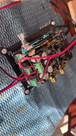
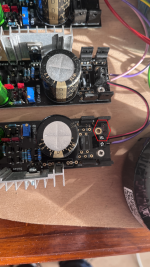
I have a problem on the negative side of the circuit. As soon as I turn on the power, small clicks appear and the printed circuit heats up at D4, you can see it in the photo, it becomes translucent.
My system must provide an analog output ian canada, the normal one, not the pro one, in 12v in 500ma, my transformer supplies in 16/0/16 and others in 9v (if it is important) and it does 80 va.
So I don't know if it's a connection error on my part, I'm not sure that's it but you can tell me, on the diagram that I made these are the 2 ways that I tried.
I had tested before without any load and I had no problems and the voltage was stable.
I also wanted to specify that the other loads of the transformer are not connected but are secure.
Attachments

- Home
- Amplifiers
- Power Supplies
- Salas SSLV1.3 UltraBiB shunt regulator