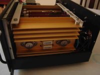
This is a request for help to the older ones here ( me too 😉 ) twho surely knew the RCA power amp based on the UAP-02 board. I'm talking about the 70's. I built the 70 Watt version of this amplifier back then, and every now and then I used it, normally I used it with my PC to feed two small speakers, so it was never used intensively or at high volumes. But, (there's always a first time) lately the left channel started to heat up so I decided to put the noble NAD 3020 in its place, and decided to see what was causing the overheating. I proceeded to check DC voltages at the output (Offset), 1.0 mV on the left channel and 9.0 mV on the right, which I considered acceptable, so the next step was to check the quiescent currents (Bias). As it was recommended in the days of analog multimeters, I did not use the typical procedure of inserting the ammeter in the collector junction of the output TRs with the + B, because the internal impedance of the same would slightly alter the measurement and this method forces us from physically opening the circuit. (Although I remember having done it on DIY - Phillips boards without problems - I do not know if using a digital multimeter the same thing happens) Applying Ohm's Law, in theory the Bias of the left channel was 41.5 mA, and of the right channel 45.9 mA, which caught my attention, I expected that the one that exceeded the maximum recommended by RCA (40 mA) was the channel that was heating up, the left one, but it is the other way around.
That said, I proceeded to adjust the presets of both channels. (RCA recommended installing a 100 Ohm preset instead of R11 in case of temperature problems.) and I managed to adjust both channels as you can see:
+B 39.5 Volts DC / 117.5 Ohms = 33.6 mA.
I was surprised that the preset allowed me to exceed the maximum 100 Ohms, but I suppose that the manufacturing tolerances in those years were quite large.
But, I was greatly surprised to find that after these adjustments, BOTH channels overheated much more, evenly and gradually, and in a few minutes!
With an ambient temperature of 27 ° C, in 10 minutes the heat sinks reached 45 ° C! The amplifier works well, and the offset now, with this temperature, is 8 mV on the right channel and 0.7 mV on the left channel.....At this point, I turn off the amplifier, the 40636 output from RCA indicates maximum 200 °C, but I won't wait to spoil them, this operation is not normal...
I really can't figure out why this can happen, I thought that some TR - input differential pair - could have become unbalanced, which usually causes anomalies in the DC output, but, that failure in both channels simultaneously? And also the DC at the speaker output is not so high...
Should I go back to the traditional Bias adjustment?
What have I forgotten in all these years ?
I will appreciate any thoughts that help !
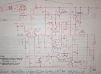
PS: The diagrams are taken from the web, the notes and measurements do not correspond to my amplifier. I will look for the original diagram and upload it, although being in red I fear that it is not very visible.
That said, I proceeded to adjust the presets of both channels. (RCA recommended installing a 100 Ohm preset instead of R11 in case of temperature problems.) and I managed to adjust both channels as you can see:
+B 39.5 Volts DC / 117.5 Ohms = 33.6 mA.
I was surprised that the preset allowed me to exceed the maximum 100 Ohms, but I suppose that the manufacturing tolerances in those years were quite large.
But, I was greatly surprised to find that after these adjustments, BOTH channels overheated much more, evenly and gradually, and in a few minutes!
With an ambient temperature of 27 ° C, in 10 minutes the heat sinks reached 45 ° C! The amplifier works well, and the offset now, with this temperature, is 8 mV on the right channel and 0.7 mV on the left channel.....At this point, I turn off the amplifier, the 40636 output from RCA indicates maximum 200 °C, but I won't wait to spoil them, this operation is not normal...
I really can't figure out why this can happen, I thought that some TR - input differential pair - could have become unbalanced, which usually causes anomalies in the DC output, but, that failure in both channels simultaneously? And also the DC at the speaker output is not so high...
Should I go back to the traditional Bias adjustment?
What have I forgotten in all these years ?
I will appreciate any thoughts that help !
PS: The diagrams are taken from the web, the notes and measurements do not correspond to my amplifier. I will look for the original diagram and upload it, although being in red I fear that it is not very visible.
Attachments
-
 2-bb163c3178.webp96.5 KB · Views: 125
 -
 circuito.jpg479.6 KB · Views: 128
 -
 amp6.jpg91.3 KB · Views: 130
 -
 Instalación fuente y Led - Potencia RCA 017.jpg135.7 KB · Views: 112
 -
 Potencia RCA 031.jpg68.8 KB · Views: 96
 -
 Instalación fuente y Led - Potencia RCA 037.jpg107.9 KB · Views: 91
 -
 Instalación fuente y Led - Potencia RCA 032.jpg108.3 KB · Views: 90
 -
 Instalación fuente y Led - Potencia RCA 007.jpg96.6 KB · Views: 88
Last edited:
Hi, Hola!!!
I assembled a lot of these boards in the 70s, it was the most affordable amp in Argentina and much better option than the others available (Texas and Philips-Fapesa).
I remember I used to do several mods; but the first one was replacing the bias diodes with a conventional Vbe multiplier, the original diodes with metal body were difficult to obtain and I felt much better having the possibility of adjusting the bias than trusting on a fixed value by design...
Best regards
Hello fellow countryman !
Yes, I also built the circuits for Fapesa, who represented Phillips in Argentina. As I mentioned, I adjusted the polarization current with analog multimeters without any problems... but I remember that an Electronic Engineer friend recommended me to make the adjustment in an "indirect" way, calculating the current by means of Ohm's Law, that's why I mention it. What method did you use?
Yes, I also built the circuits for Fapesa, who represented Phillips in Argentina. As I mentioned, I adjusted the polarization current with analog multimeters without any problems... but I remember that an Electronic Engineer friend recommended me to make the adjustment in an "indirect" way, calculating the current by means of Ohm's Law, that's why I mention it. What method did you use?
The pictures you provided do not show how big your heat sink is, nor whether the mica pad and thermal grease are any good after these years. I found the heat sink in my dynakit ST-120 that used 40636 outputs was totally inadequate for anything but the FTC one hour test, and changed over to two salvaged from Pentium II computers. 2 cm x 10 cm x 6 cm with about 6 fins.
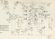
None of the quasicomp designs of those days have an emitter resistor on the bottom output transistor. Diagram 3 and your later diagram do not have one. You could get away with that with real 60636, 1C05 or other homotaxial transistors, but anything epitaxial like TIP3055 MJ802 or later requires an emitter resistor to not run away thermally. Modern stock labeled 2n3055 is not homotaxial and requires emitter resistor protection. The old RCA factory is now a county park in New Jersey.
Unusual heating can be ultrasonic oscillation. If your analog VOM has 20 vac scale, block the negative probe with a 390 pf capacitor 50 v or higher. Connect that to speaker ground and plus to speaker hot. If you are getting significant AC voltage, it has to be ultrasonic because 390 pf will not pass music frequencies. Note the Simpson 266-XLPM I own will read voltage below 0.7 vac because it has a selenium bridge, not silicon diodes.
BTW if you want to signal trace, exercise input with a FM radio turned down to 1/3 to produce 1.5 vac music. Block the negative probe on 20 vac, or 2 vac on the front end, with a .047 uf 100 v or more capacitor.
Yes, when setting idle bias current I short the input then read DC voltage on one of the emitter resistors of an output transistor. R23 or R22 of your last schematic diagram.
Last edited:
As long as the PNP driver emitter is tied to the output collector, and both are run through the “emitter” resistor in the collector of the lower output, an additional resistor in the emitter is unnecessary. The lower output is a bog standard CFP, and that’s where the resistor usually goes when CFP is used in a complementary design.
In other RCA designs multiple outputs are paralleled. Since this requires ballasting, the resistors are put in the emitter, and the driver emitter is tied directly to the speaker out (through the Baxandall diode, if one is used). This configuration can be used with only one output device - it’s just not used here. The emitter resistor goes in one place or the other. Both result in slightly different “negative half” characteristics. Neither is exactly the same as the positive half.
As far as thermal stability, it’s the total emitter resistance that matters. One side doesn’t even need one, if the other is doubled. This however, results in more distortion.
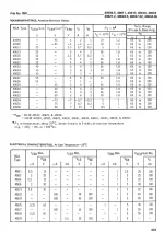
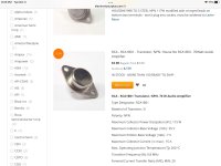
@indianajo - this may be the one you’re thinking of. 1B01 is the hometaxial “super 2N3055”, similar to 40636. IIRC, the 1C04/5 were the complementary drivers for it. 1B05 is the high voltage one, and is a multiple emitter expitaxial type. Still has crazy high SOA but is only good for 5A.
Attachments
How many NTE60 (1988) or other MJ15003 copies have you burnt up? My count is 4, driven by the dyna PC-14 with only one emitter resistor. Apex AX6 has an emitter resistor on both output transistors. As does the PC-14 side of my ST-120 these days. No telling whether the second emitter resistor or the fans stopped the damage.As long as the PNP driver emitter is tied to the output collector, and both are run through the “emitter” resistor in the collector of the lower output, an additional resistor in the emitter is unnecessary.
My RCA catalogs totally skip the 40636 1A 1B 1C days. Sorry. Why the 70 w -6 amp schematic has 1C05 is a mystery to me.
Last edited:
The easiest way is measuring the voltage drop across the emitter resistors of the output transistors.Hello fellow countryman !
Yes, I also built the circuits for Fapesa, who represented Phillips in Argentina. As I mentioned, I adjusted the polarization current with analog multimeters without any problems... but I remember that an Electronic Engineer friend recommended me to make the adjustment in an "indirect" way, calculating the current by means of Ohm's Law, that's why I mention it. What method did you use?
If you replace the string of diodes by a Vbe multiplier, you will be able to adjust it to the chosen value, it is better to do it without any load connected to avoid error caused by the small offset voltage at the output.
Time and thermal inertia also play in the adjustment, the transistor used for the Vbe multiplier can be glued on top of the output transistors.
At that time, I only had an oscilloscope, so I increased the idle current until the crossover distortion "disappeared" on the screen.
How many NTE60 (1988) or other MJ15003 copies have you burnt up? My count is 4, driven by the dyna PC-14 with only one emitter resistor. Apex AX6 has an emitter resistor on both output transistors. As does the PC-14 side of my ST-120 these days. No telling whether the second emitter resistor or the fans stopped the damage.
My RCA catalogs totally skip the 40636 1A 1B 1C days. Sorry. Why the 70 w -6 amp schematic has 1C05 is a mystery to me.
The -6 isn’t 70W, it’s only +/-26V and uses the TO220 output types. They can of course be used as rugged drivers (more rugged than 40409/10). My current RCA catalog is missing most of the 1A 1B 1C stuff too, but an old one I had years ago had it all. Back when the 40411 was the primo 2N3055-oid. This one from 82 doesn’t have the 40411 in it anymore.
For the circuit in question R22 is the emitter resistor in the lower half. I’ve seen plenty of stable circuits using only one side. They increase the value to 1 to 1.5 ohms. 0.22 to 0.33 isn’t enough. And ALL of those were single supply so it never tried to force the output to zero volts, either.

AnibalThe easiest way is measuring the voltage drop across the emitter resistors of the output transistors.
If you replace the string of diodes by a Vbe multiplier, you will be able to adjust it to the chosen value, it is better to do it without any load connected to avoid error caused by the small offset voltage at the output.
Time and thermal inertia also play in the adjustment, the transistor used for the Vbe multiplier can be glued on top of the output transistors.
At that time, I only had an oscilloscope, so I increased the idle current until the crossover distortion "disappeared" on the screen.
It's good advice but I didn't take it into account for three reasons.
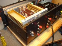
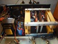
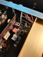
1) The amplifier is assembled in a way that is very uncomfortable for working and accessing the connections between the output transistors and the diodes mounted on the heatsink and the board, you can see in the photos that everything is very "compressed". Any intervention requires disassembling the UAP-02 boards, making the connections for the VBE compensator that you propose (I have read about it in the link that I attached) and reassembling everything, a job that I was not willing to do on an amplifier that has only a "nostalgic" value for me.
2) In that same local forum in Argentina I refreshed several concepts and about this RCA x 70 Watts amplifier they convinced me to insist with the quiescent current by adjusting the 100 Ohms preset that replaces R11 (47 Ohms)
3) Finally, I thought that if this "creature of youth" worked well for 50 years without overheating, I would have to insist without modifying anything or replacing components at random.
https://www.forosdeelectronica.com/threads/corriente-de-reposo-en-amplificador-de-70w-rca.152851/
Rolando
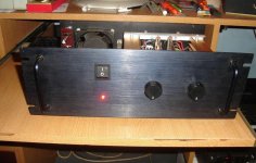
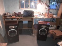
As you can see in the pictures above, the heatsinks I used at the time are extruded aluminum heatsinks with good performance, the problem was that I couldn't place them vertically, which would have been ideal, because they didn't fit inside the cabinet.The pictures you provided do not show how big your heat sink is, nor whether the mica pad and thermal grease are any good after these years ...........
The cabinet is 35.5 cm wide x 20 cm deep x 14 cm high
Each heatsink measures (Taking the position inside the cabinet)
15 cm deep x 11 cm high x 3.2 cm wide
Anyway, you'll see that the problem wasn't the heatsinks, let me give you a little suspense on this, because I've been lucky in the arrangement and I don't want to end the thread so soon! ....😉
I took this picture a few moments ago in my "man cave", (very messy, yes...) you can see the amp being tested with some Technics SB1950s....hey, that's the year I was born ! 😳
Attachments
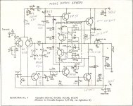
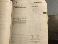
Yes, actually the circuit I attached (in red) already had the latest updates from RCA in those years. It corresponds to a bulletin from Eneka, distributor here of the plates and components to assemble the amplifierit ( was not a kit ) , is from August 1977. On the advice of my friend David that I mentioned before, (who checked in the oscilloscope that there were no oscillations in the output), only two 47 Pf capacitors were added to this diagram between C and B of Q4 and Q5, and 18 Pf in parallel with R6. Don't ask me what function they perform, I have forgotten and currently I have no more contact with him, he moved to Barcelona, Spain. A pity, because he was my consultant here and he really knew a lot....🙄The -6 isn’t 70W, it’s only +/-26V and uses the TO220 output types.....
Last edited:
50 pf c to b on the drivers were added in the "TIP mod" to the dynaco ST-120 which also used quasi comp homotaxial output transistors. My shorted TO3 transistor were dynaco house number marked so no telling if 40411 40636 or 2n3773. I got the number 40636 from the Armstrong 621 schematic, dynaco never revealed their part secrets. Cap parallel to R6 is called "compensation" and has something to do with preventing feedback oscillation. My ST-120 had no feedback transistor Q2.only two 47 Pf capacitors were added to this diagram between C and B of Q4 and Q5, and 18 Pf in parallel with R6.
Sorry I did not spot the heat sinks picture lower left of post #1. Enthusiastically large.
I have been known to attach a cinch terminal strip to the chassis somewhere convenient, and run a couple of wires from both ends of an emitter resistor to the terminal strip. For measuring idle O.T. bias current, as voltage. I've had no trouble with the ST-120 idle current running away with an Apex AX6 board, putting the 2 sense diodes on a cinch terminal strip above the output transistors mounted on the wimpy Dynaco heat sink (aluminum angle). I do clamp the series potentiometer with a schottky or regular diode, as appropriate, to keep idle bias from running high if the pot wiper loses contact. Peavey controlled idle bias current in PV4c and PV-1.3k by carefully matching and gain selecting all transistors. and a repair person cannot assume the same current results with random parts bought from distributors. Peavey still used temp sense double diodes (called a stabistor) in the 90's, burying them in the heat sink in thermal glue. There was a fixed resistor in the diode stack.
Last edited:
Interesting tips from Dynaco. By the way, I think the amplifier that became most popular using this RCA circuit was the Harman Kardon Citation 12. With some modifications that can be seen here.
https://www.updatemydynaco.com/Citation12.html
https://www.updatemydynaco.com/Citation12.html
Last edited:
Bueno, volviendo a mi problema, parece que tuve un error al intentar ajustar la corriente de reposo. Pensé que R11 se insertaba directamente entre el colector de Q6 y VCC, y no es así, ajusta el driver de Q6, es decir Q4. Al observar el circuito observé esto y me equivoqué...:ups:
Así que ajusté el valor predeterminado de 100 ohmios a 45 ohmios en cada canal y todo volvió a la normalidad. Tenga en cuenta que es ligeramente inferior al valor original de R11, es decir, 47 ohmios. No hubo más sobrecalentamiento, la temperatura en cada disipador de calor después de un largo tiempo de reproducción de música (con una temperatura ambiente de 25 °C) es de 33 °C a un volumen medio.
¿Y cuál es entonces la corriente de reposo real? Bueno, no más cálculos ni mediciones por ahora, ¡hoy es Navidad!
¡Todo lo mejor para todos ustedes en este día!🙂
Attachments
Sorry, I copied the GT translation wrong......
Well, back to my problem, it seems I made a mistake when trying to adjust the quiescent current. I thought R11 was inserted directly between the collector of Q6 and VCC, and it is not so, it adjusts the driver of Q6, i.e. Q4. Looking at the circuit I noticed this and I was wrong...😳
So I adjusted the default value of 100 ohms to 45 ohms on each channel and everything was back to normal. Note that it is slightly lower than the original value of R11, i.e. 47 ohms. There was no more overheating, the temperature on each heatsink after a long time of music playing (with ambient temperature of 25°C) is 33°C at medium volume.
And what is the real quiescent current then? Well, no more calculations and measurements for now, today is Christmas!
All the best to all of you on this day! 🙂
All the children grandchildren and greatgrandchildren have repiratory infections. The wife is totally immune, Ukrainian-French ancestry, and is over there celebrating Christmas with them. I as a grandson of a native American that died of a bad cold age 42, am going to receive dinner leftovers in a couple of hours. Enjoy your family holiday.
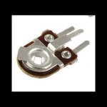
If R11 is a potentiometer that shorts one end to the wiper, then that is subject to opening up when the wiper oxidizes in 5 to 20 years. The resistance then goes maximum value. 45 versus 47 would net be dangerous, but any value below that, I would clamp R11 end to end with a 1n4148 or schottky diode (0.3 v) as appropriate to prevent thermal overload.
You will notice R11 d2 d3 d4 form a stack driven by the VAS Q3. This makes the base of driver Q4 more than 2 v above the base of driver Q5. This approximates the 4 diode drops Q4 Q6 Q7 Q5 necessary to keep both output transistors on slightly at the same time.
Q8 Q9 appear to be VI limiters, that limit base drive current to the drivers if the currents in R23 R22 get too high. Kind of a frill on an amp this low power.
In 1971 when I had enough money to shop for a stereo better than my Mother's LP ripper RCA with 2" woofers and 2 12AX7, Harman Karden was a brand of receiver that wore out the pots and switches in less than a year. Lots of fellow students had them. I had no idea Harman Karden had ever been a quality brand until a thread on the Citation 12 came up on diyaudio a couple of years ago. I never looked for one in shopper papers. I never encountered a burnt hulk on the back shelves of a hifi shop. Probably all Citation 12 were snapped up by rebulders and sold for 75% of new price. In 1971 I bought a dynaco PAS2 preamp and ST70 amp, the same brand that the university library was running 16 hours a day. The 6CA7 tube ST70 was a much better amp than the 40411 ST-120, but by 1985 I could buy no output tubes or 7199 inputs. So I bought the ST-120 hulk in 1986 for $50. With AX6 driver boards instead of dynaco PC-14 it produces quality sound. The first time I repaired it no schematic diagrams were available. I could not even determine if the limiter TO3 Q9 was npn or pnp! first result was a 20 watt/ch amp due to too much limiting from Q9.
Last edited:
Reading in some books I updated my somewhat forgotten knowledge:
" Depending on the type of circuit, the quiescent current is normally between 20 to 45 mA "
" If it is less than the minimum recommended, the amplifier will have crossover distortion, and this will mainly affect the low frequencies "
" If it is greater than the maximum recommended, the amplifier will enter thermal runaway "
" The voltage drop across the emitter R must be exact or at least approximately equal in each of them."
So, in this quasi-complementary symmetrical RCA circuit, we have a recommendation of 20 to 40 mA, so I proceeded - with some patience and a lot of care not to cause any short circuits with the multimeter tips - to adjust the two channels to the following values.
Left channel :
R22 = 95 mV / 0.33 Ohms = 28,7 mA
R23 = 93 mV / 0.33 Ohms = 28,1 mA
Right channel :
R22 = 97 mV / 0.33 Ohms = 29,3 mA
R23 = 96 mV / 0.33 Ohms = 29,0 mA
Finished the work, thanks for stopping by. 🙂
PD: The temperatures have risen slightly compared to those taken in post 18.
- Home
- Amplifiers
- Solid State
- Vintage board UAP-02 - RCA 70 Watts - Temperature problems