I have no clue but it seems linear,has anyone tried 6e5p tube for i/v stage ?
150V targett B+ ? 47 Mu in triode mode ... what not o like ? (osci ?) ... perhaps the challenge to find two close enough according the circuitry you choose. Not a Vladivostok to Moscow mismatch window
in which way, exactly?
We need your vaudo for a mosfet or emitter input BJT/BPC single ended (Papa's redo was for balanced output iirc) 🙂 !
Btw Zoran here proposed a discrete here but I do not remember where (not linked on the blog at least)

certainly less lost time than 5532 whatever it is a good Signaletic (I am jealous though for the stack Exchange thing here ! But the AD8567 should beats it hands in the pocket for I/V but I never tried, there are so way better than AD797 op amps types for the I/V task imo ! )
But do you really want a passive I/V with a resistor and a gain tube nowadays ? Is it the best way to make it linear current to volt conversion for a dac chip ? 😉
As someone had the idea to try the op861 in emitter input mode with Super reg blah and some 1/8 W AB resistor at output or more if a buffer in between ? and a smooth one as I/V resitor (AB for its good carbonn comp behavior here or a no so ideal Ayrton Perry but one that is good here (not the Vishay please) Rhopoint or hand made by virgins like John from ECDESIGNS? or even the non inductive Vishay Grunf talked but here as I/V if smd layout ?....
😎😛🥷😊
@EDITH: I was advised OPA856, but with a red Alert about the cares to avoid osci !
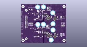
The pcb has also uf-l outputs if someone asks at the back.
But do you really want a passive I/V with a resistor and a gain tube nowadays ? Is it the best way to make it linear current to volt conversion for a dac chip ? 😉
As someone had the idea to try the op861 in emitter input mode with Super reg blah and some 1/8 W AB resistor at output or more if a buffer in between ? and a smooth one as I/V resitor (AB for its good carbonn comp behavior here or a no so ideal Ayrton Perry but one that is good here (not the Vishay please) Rhopoint or hand made by virgins like John from ECDESIGNS? or even the non inductive Vishay Grunf talked but here as I/V if smd layout ?....
😎😛🥷😊
@EDITH: I was advised OPA856, but with a red Alert about the cares to avoid osci !
The pcb has also uf-l outputs if someone asks at the back.
Attachments
Last edited:
I tried them once, like many others, but I wasn't convinced. I'm staying with the ECC40.I have 4pcs 6E5P well matched. Maybe I'll try that too.
I only tried them on an oscilloscope. 😊 I didn't have a chance to hear them. It was a small assembly made for testing a large number of 6E5P in triode mode, but only one channel on the raster board and SMPS power supplies 6.3V and 265V.
There is no need for a 6e5p in the DAC (only perhaps for the output buffer), for the I/V stage an ECC88 is perfectly fine.has anyone tried 6e5p tube for i/v stage ?
I'm still considering I/V with E180F in triode for gain + 6E5P for CF ( also in triode ) but need to refine the circuits and if i want any kind of regulation ( beside Maida series reg ) will need a new power trafo ( not a problem ). For AD1865.
With E180F in triode i think lower value resistor for R/V can be used especially since i do not need full 2 Vrms at output.
Have six 6E5P from the batch that Nixie measured - at the current from 15-20 mA per tube methinks oscillaton could be real possibility if the layout is not done properlly.
CF is mandatory for me currently otherwise i would go ( and maybe anyway will try ) Michelag's pcb ( Grunf's circuit ).
???I didn't have a chance to hear them.
I'm sure you've heard them.
I agree that with a reactive impedance of an IV stage, DAC will see different load at different frequencies and that will result in complex distortions. However, I suspect that with a low non-reactive Riv, high impedance of an IV transformer should not make a difference.When connected like this, DAc Iout is directly and heavily loaded with huge reactances. From primry and additionaly from transfered secondary side. And losses will be huge. Also it is useful to simulate this configuration against Riv first at primary and compare results...
.
When Riv is at the output of DAc Io, we also have reactive load componenet as parallel complex componenet but in parallel with lower value of Riv. (In that case it is almost irrelevant internal reactive component, non-inductive etc, of the Riv because a much larger are already present from the succeeding transformer...)
.
All in all the best way for using a non reactive Riv is
to aply non-rective very low inductance and very low capacitance R @ DAC Iout
then go to low output impedance buffer to isolate ractive component from DAC Ioutput (in that case we have only few pF and no dynamic capacirtance at the DAC output, so rective component is completly minimized.
after thet connect the transformer. Thansformer will have prppper low impedance drive, LF chrs will be much better, THD will better and HF will better too...
then measure with square wave, and RC terminate secondary for riging, use higher termination load.
The another buffer with separate PS after the secondary is na option, this time to mimize influence of the capacitive load to the secondary...
This way DAC as DA system is compleatly galvanicaly isolated from pure Analog domain. As main feature of transformer as isolation element...
🙂
I think Sowter recommends to put Riv on the secondary https://www.sowter.co.uk/dacs.php. I really do not understand why. Your experience makes sense to me,My experience is with @NIXIE62 transformers rewound from a local craftsman Đole. First it was connected 1:9 and the RIV was on secondary and the sound was better than OPamps. I tried different values for RIV mresistors and the lower the value the better the it sound. Connected the trafo to 1:18 and reduced the RIV to secondary and the sound was better. There is no gain for direct drive amps so I go through tube preamplifier (Kondo M7 clone with ecc82). In the end, when we compared it with a Lampizator DAC, the owner remembered that Sowter said to put 47K on the secondary and 25R on the primary, so we changed it and it was the best PCM63 sound I've heard (pcm63+trafo IV+c3g+AVC to amp). I ended up having to upgrade my Kondo M7 clone, paralleled the Mundorf MCap Supreme output capacitors with the Duelund Alexander and added capacitors to cathode resistors and get more gain.
It doesn't need any buffer behind that transformer?
I'll probably try something but as it sits, the circuit doesn't appear to need one. It will most likely depend on if I include a line stage in the final chassis.
Hi, I’m using Sowter 1495 with 100R I/V resistor on primary side, but when I connect the transformer with parallel secondary 1:9 configuration, the output is low ( about 400-500mV RMS) when I connect it with serial configuration 1:18 then the frequency response is limited and start to drop at 2kHz.
I'd suggest 1:9 and loading the secondary as the datasheet indicates... it's working quite nicely with this model, no reason to think it wouldn't with the 1495.
In your case how big is the I/V resistor and how big is the output (RMS)
Have you measured how the frequency response looks like?
4.3K I will experiment a little, but so far this seems great. No issues in the high frequencies at all.
I have not done any official measurements yet, it's only been together a short while.
As for the loading resistor on the secondary, this is not unlike a SUT for phono, where the reflected load is important to the source and also controls the ringing of the transformer. It will be interesting to measure and compare the DAC with the standard opamp I/V and the one with transformer I/V.
Guys try this my very cheap I/V and compare it to pricey opamps, it is time for cheap christmas presents 🤣 
I/V based on TPA6120
edited post #9463 (added R3, R4 on the output signal, hole in the GND under the feedback trace)
Power supply range is from +-5V up to +-15V. It can be powered directly from DAC PSU.
R1 and R2 value determines the output voltage. For a higher output voltage use higher value of this resistor (1k5 == 1.5Vp, 2k7 == 2.7Vp, ...).
R3 and R4 resistors melf 0204 or SMD1206, value 22R up to 100R.
Capacitors are polypropylene and a high quality electrolytics (UKW from Nichicon is still available).
There is hole in thermal pad under the IC, where you solder the IC...
Attachments

I haven't listened to that test circuit with the 6E5P, that's what I mean. It was just made for a measurement.???
I'm sure you've heard them.
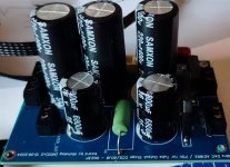
What is the nominal current of that HV secondary?Now to my question, what value fuse should I use?
It's on the low side, but should work. 200vac 0.03AWhat is the nominal current of that HV secondary?
Yes 6E5P in triode mode is very linear. And can be used as amplification stage after Riv at the output of the current dac.I have no clue but it seems linear,
Amplification factor is about 32 times, so it is enough to use with lower value of Riv.
Interna resistance is about 1.1K which rougly in parallel with Anode load giving lower than 1K output resistance, so tube can be used without buffer.
A high transconductance is allowing to use this tube even in the grounded grid configuration.
Low internal resstance in this case has additional benefit to use this tube with L load, because this L is not from very high inductance and it is not complicated to mount or find apropriate in the stores. For very good LF and HF response...
.
If i find some time window I will post the spice circuits
cheers
.
And also I somehow find that these obsolete specific types from Signetics classic 5532 are better than contemporary?
I cant explain what ii is about, But I am remebering that I exidently tried, before many years when thesting some DACs, that old Signetics types pulled out from some philips CDs are better sounding than almost any in that moment contemporary type.
But that was before many of these new OP amps produced? Also original TI version BUT from SMD package 5532 where close to Signetics
Anyway worth to try.
- Home
- Source & Line
- Digital Line Level
- DAC AD1862: Almost THT, I2S input, NOS, R-2R