I’m building a stereo amplifier with 2 x KT150 in Push-Pull. One channel is finished and working properly. The second channel is almost done, but starts oscillating loudly at approx. 1.5 kHz..
I’m working on this problem now for more than a month. When testing I have to use hearing protection, as it oscillates really loud. I tested and tried a lot and I’m about to give up on this. It seems I have created a very stable and very reliable oscillator ☹.
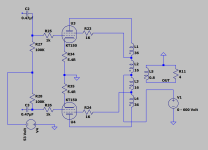
The diagram is actually very simple, see attachment. The driver stage (not shown in the diagram) is disconnected and not powered to make sure it’s not the cause of the oscillation.
Normally the B+ is around 560 Volt and bias voltage is coming from an automated bias board. Due to the oscillations I’m testing now with a variable B+ (0 - 600 VDC) and a fixed negative voltage of 53 VDC. I’m using separate lab supplies for these test runs. This excludes the amplifier’s B+ and bias supply as a source for the oscillation.
Some comments / remarks:
- oscillation happens only with a speaker connected, NOT with a dummy load connected. I tested with several speakers and all speakers cause this oscillation.
- oscillation happens in UL mode and in TRIODE mode (G2 to plate, with 1K still in place).
- oscillation does NOT happens in PENTODE mode (still with 1K in place for G2). I can go all the way to 600 Volt without oscillations.
- I checked over and over that the screen, cathodes, grids and plates are not cross-wired between the two tubes. They are NOT.
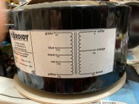
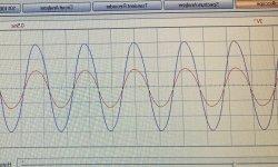
- I checked the OPT using a 1 kHz. signal on the 4 Ohm tap, measuring the amplitude and phase on the primary windings of the transformer. The phase measures OK for each side / tube and the amplitude on the UL tap is lower than on the plate tap. See image attached. All measurements are according to the label on the transformer (see attachment). I checked the other channel’s transformer as well, and the results are similar / identical.
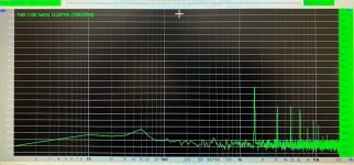
- On the attached recording I start with a voltage of 390 Volt and go slowly to 410 Volt, back to 390 Volt and again to 410 Volt. Oscillation starts around 395 Volt. This is with UL mode. Of course the voltage causing the oscillation is depending on the bias voltage. And with TRIODE mode it’s different again (but it will definitely oscillate with a certain B+). On the spectrum analyser’s screenshot you can see the oscillation’s frequency and harmonics.
- The oscillation frequency is somewhat depending on the output transformer’s load. With a 4 Ohm speaker it’s around 1.5 kHz. With an 8 Ohm speaker (B&W) the oscillation’s frequency rises to around 2 kHz.
- The speakers are NOT near the output transformers. With 5 meter distance the oscillation remains the same. Shielding the transformer or changing the speaker’s direction does not make any difference. Using alternative temporary wiring to the speaker makes no difference.
- carefully moving or touching the wiring in the amplifier and to/from the amplifier has no effect.
- changing tubes from the left channel to the right channel has no effect.
- careful matching of the KT150 tubes does not make any difference.
- lowering the G1 resistors from 100K to 50K makes no difference.
- placing a temporary (grounded) shielding between the two KT150 tubes makes no difference.
- I checked multiple times with and without measuring equipment (scope, wattmeter, soundcard, voltmeter, etc.) attached. Again this makes no difference.
- I tried grounding one of the output transformer’s wires to ground. Grounding / not grounding one end of the output winding makes no difference.
What can cause these oscillations? What else can I try?
Regards, Gerrit
Edit: Zip-file with .m4a audio file added.
I’m working on this problem now for more than a month. When testing I have to use hearing protection, as it oscillates really loud. I tested and tried a lot and I’m about to give up on this. It seems I have created a very stable and very reliable oscillator ☹.
The diagram is actually very simple, see attachment. The driver stage (not shown in the diagram) is disconnected and not powered to make sure it’s not the cause of the oscillation.
Normally the B+ is around 560 Volt and bias voltage is coming from an automated bias board. Due to the oscillations I’m testing now with a variable B+ (0 - 600 VDC) and a fixed negative voltage of 53 VDC. I’m using separate lab supplies for these test runs. This excludes the amplifier’s B+ and bias supply as a source for the oscillation.
Some comments / remarks:
- oscillation happens only with a speaker connected, NOT with a dummy load connected. I tested with several speakers and all speakers cause this oscillation.
- oscillation happens in UL mode and in TRIODE mode (G2 to plate, with 1K still in place).
- oscillation does NOT happens in PENTODE mode (still with 1K in place for G2). I can go all the way to 600 Volt without oscillations.
- I checked over and over that the screen, cathodes, grids and plates are not cross-wired between the two tubes. They are NOT.
- I checked the OPT using a 1 kHz. signal on the 4 Ohm tap, measuring the amplitude and phase on the primary windings of the transformer. The phase measures OK for each side / tube and the amplitude on the UL tap is lower than on the plate tap. See image attached. All measurements are according to the label on the transformer (see attachment). I checked the other channel’s transformer as well, and the results are similar / identical.
- On the attached recording I start with a voltage of 390 Volt and go slowly to 410 Volt, back to 390 Volt and again to 410 Volt. Oscillation starts around 395 Volt. This is with UL mode. Of course the voltage causing the oscillation is depending on the bias voltage. And with TRIODE mode it’s different again (but it will definitely oscillate with a certain B+). On the spectrum analyser’s screenshot you can see the oscillation’s frequency and harmonics.
- The oscillation frequency is somewhat depending on the output transformer’s load. With a 4 Ohm speaker it’s around 1.5 kHz. With an 8 Ohm speaker (B&W) the oscillation’s frequency rises to around 2 kHz.
- The speakers are NOT near the output transformers. With 5 meter distance the oscillation remains the same. Shielding the transformer or changing the speaker’s direction does not make any difference. Using alternative temporary wiring to the speaker makes no difference.
- carefully moving or touching the wiring in the amplifier and to/from the amplifier has no effect.
- changing tubes from the left channel to the right channel has no effect.
- careful matching of the KT150 tubes does not make any difference.
- lowering the G1 resistors from 100K to 50K makes no difference.
- placing a temporary (grounded) shielding between the two KT150 tubes makes no difference.
- I checked multiple times with and without measuring equipment (scope, wattmeter, soundcard, voltmeter, etc.) attached. Again this makes no difference.
- I tried grounding one of the output transformer’s wires to ground. Grounding / not grounding one end of the output winding makes no difference.
What can cause these oscillations? What else can I try?
Regards, Gerrit
Edit: Zip-file with .m4a audio file added.
Attachments
Last edited:
Fit a Zobel network to the output.
Try swapping the output polarity (and swap at the speaker too.)
Try swapping the output polarity (and swap at the speaker too.)
Just out of curiosity.......
Is this 2 circuits on the same transformer?
If not, try to swap the output transformers between left and right, just to eliminate the possibility of a faulty transformer.
Usually, Toroidy´s TF´s are excellent quality, but..... these are made by humans, and as such in the range of human error, core wise,
winding wise etc.
Hi Boydk, both transformers measure the same. I haven’t swapped them, but they measure identical (both in phase and amplitude) and in dc resistance.
Swapping the transformer is a lot of work within a tight enclusure and all the shrinkshield applied on tube sockets, switches, etc..
Regards, Gerrit
Swapping the transformer is a lot of work within a tight enclusure and all the shrinkshield applied on tube sockets, switches, etc..
Regards, Gerrit
Hi Batteryman,
I guess you mean a zobel between the two plates? Any suggestion for component values?
Regards, Gerrit
I guess you mean a zobel between the two plates? Any suggestion for component values?
Regards, Gerrit
Interesting the oscillation comes on gradually so probably not breakdown. If you simply put a 500Hz waveform into the primary of the transformer what do you see on the secondary into 8R. Something must a quite wrong for this to happen. Could you post a complete schematic with no driver but with the power supply, or are you running off a bench supply.
Hi Baudoin,
I'm sure if I put 500 Hz. in I will get 500 Hz. out (with a much lower voltage since it's a transformer). And the transformer measures OK. Of course I can do this test, but with which intention? Where should I look at?
Regarding your second question: I'm not using the amplifier's PSU (for now), but bench supplies to rule out that the PSU is part of the problem. I have a Xantrex 19" bench power supply for 0 - 600 VDC @ 2Amp max. I can vary the voltage very simple with this supply, much easier than with the amplifier's supply. There is a very thin line between silence and oscillation. In the test setup it's silent around 390 Volt and oscillating loud at 392 Volt. This is so weird.
Regards, Gerrit
10r 2-3WATT IN SERIES WITH 100NHi Batteryman,
I guess you mean a zobel between the two plates? Any suggestion for component values?
Regards, Gerrit
Are you sure the screens are connected right? Maybe the OT is constructed wrong, try swapping the screens.

Those values might work at the output (OT secondary).10r 2-3WATT IN SERIES WITH 100N
Certainly not between the plates. Would essentially mean an AC short there.
Sorry to check you get a square wave out, rather something which is ringing. Your probably correct but its a case of checking everything. Something is wrong not sure what. Sometimes its something you are not considering like say a shorted speaker cable or creating a current loop with the speaker connected. Your in the 1 in 1000 of something wrong. A circuit like that should be not near instability. That why a photo would be good.
Last edited:
The NFB lowers powerstage gain.
To check for correct phase, disconnect the NFB and see if signal/gain increases.
To check for correct phase, disconnect the NFB and see if signal/gain increases.
A zobel network is for the secondary. Sorry, didn't see the OP's mention of plates which would be the wrong place for it.Those values might work at the output (OT secondary).
Certainly not between the plates. Would essentially mean an AC short there.
Yep its possible that its actually oscillating at 130KHz or so in UL, but triode mode? The speaker may well have a max impedance at 1-2KHz.
A Zobel (aka Boucherot) network can be used at the OT primary or secondary.A zobel network is for the secondary. Sorry, didn't see the OP's mention of plates which would be the wrong place for it.
Of course component values need to be adjusted according to the OT impedance ratio.
First of all thanks for all contributions and comments.
1. I will try a Zobel on the secondary tomorrow and report back here.
2. I will use a 500 Hz. sine wave signal on the OPT’s primary and measure on the 8 Ohm output. I will look at the waveform.
3. I don’t use GNFB at all (see diagram), the only FB is from UL or TRIODE mode, so there’s nothing to disconnect.
4. How could a 130 kHz oscillation become audible like 1550 Hz.? I don’t see the link here.
5. There is definitely no short “turn” by the toroid’s mounting bolt.
6. Grounding C2 and/or C3 makes no difference.
7. The screens are connected properly (I checked that over and over and redid most of the mouting / soldering to be sure); the transformer’s measurements confim this as the phase, amplitude and DCR are correct and similar to the other - perfectly working - channel.
Of course my mind is constantly going over the circuit and I will look at all your suggestions, again and again. I want to find out what’s causing this.
Regards, Gerrit
How can you quite sure it´s the rack PSU that isn´t oscillating ? There is no B+ electrolytic capacitor shown on the drawing. HV psu´s do have low output impedances but also feedback gain elements, which can oscillate when gain/ phase from elsewhere add. The other issue is to lower the grid leak resistors to 50K and check again. I would even mention have you wired the IO valve holders correctly ?
Start with a lower B+ to avoid any damage.
Bench Baron
Start with a lower B+ to avoid any damage.
Bench Baron
- Home
- Amplifiers
- Tubes / Valves
- KT150 Push-Pull audio frequency oscillations